YSI_Prog_E - 第174页
4-14 4 Inspection status 1.5 Solder Quantity Check T his inspection status is used to detect solder fillets on chip parts, and to inspect solder quantity . 1 Make a "step" setting. 1. Create a step frame. 2. Op…
4-13
4
Inspection status
4
Perform a step test.
1. Press the [Step] button at the "Tuning" tab to perform a test for the created step.
2. When the test result appears, press the [End] button. When doing so, there is no problem if the test
result is "NG".
5
Press the [Detail] button.
A "Test Results" screen appears. Take a note of the results and check.
1. The detected character and recognition score (%) are displayed in order of highest degree of
recognition.
2. Review the "Min Score" setting in the judgment conditions parameters based on the recognition
score result.
3. By pressing the [Auto Calculation] button, the following detection conditions parameters are set
automatically.
Character Size X (mm)
The maximum X width in the test results is set.
Character Size Y (mm)
The maximum Y width in the test results is set.
TIP
Depending on the recognition status, there may be times when the "Character Size X, Y (mm)" is best left at "AUTO".
6
Perform a step test again.
1. Press the [Step] button at the "Tuning" tab again to perform a step test.
2. Take a note of and check the detection data, and then press the [End] button.
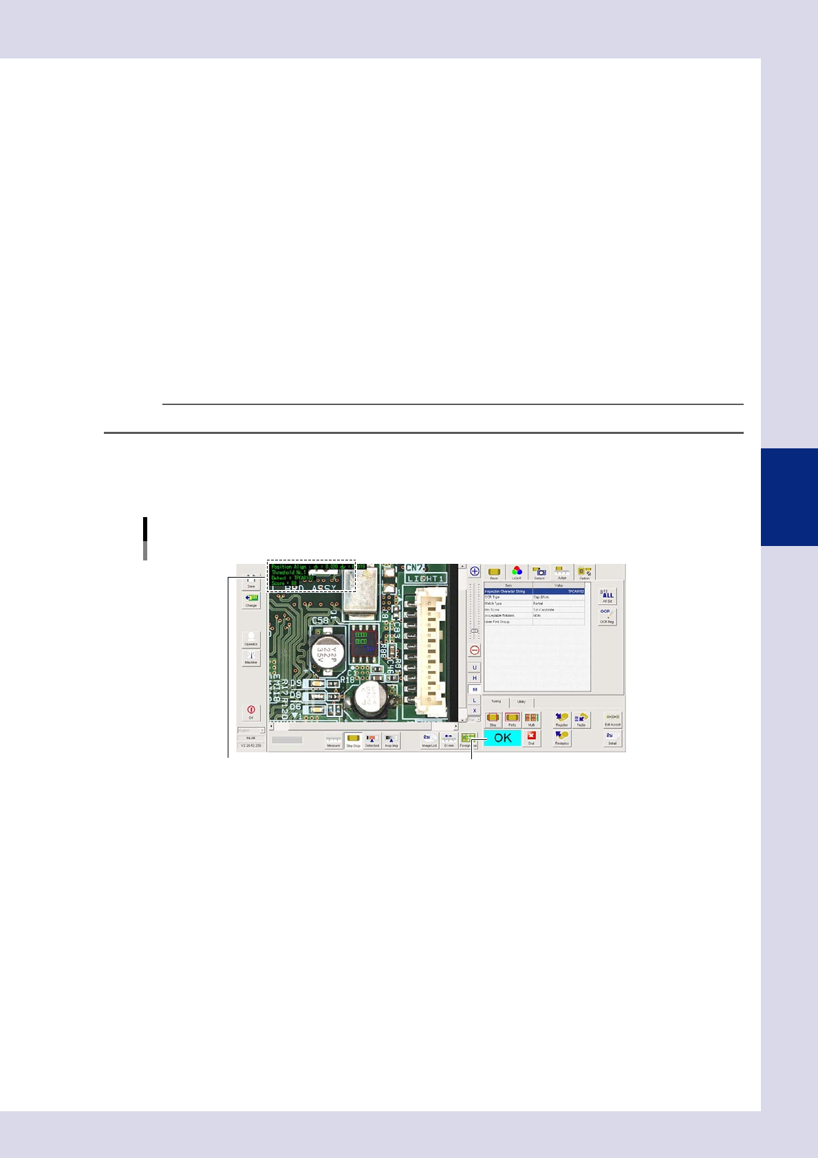
Screen after a step test is finished
Test resultDisplays detected data.
24418-P6-00
Detected data
Threshold No. : Threshold No. used for inspection
Detect : This is the recognized character.
Score : This is the minimum recognition score for recognized characters.
3. If the test result is not judged correctly, review all parameters while referring to the detection data.
4-14
4
Inspection status
1.5 Solder Quantity Check
This inspection status is used to detect solder fillets on chip parts, and to inspect solder quantity.
1
Make a "step" setting.
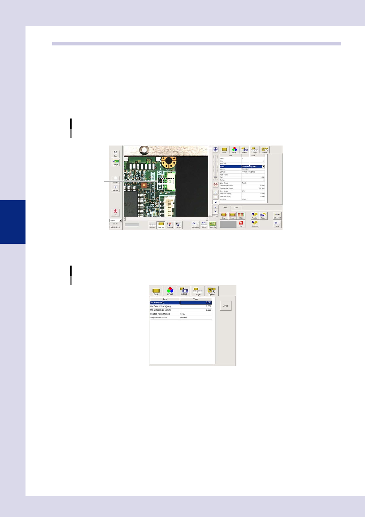
1. Create a step frame.
2. Open the "Basic" tab, and set the "Status" in the basic parameters to "Solder Quantity Check".
3. Open the "LIGHT" tab, and set the light sampling type and threshold value in the lighting parameters
so that fillets are shown in red.
Sampling light type reference: Shape
Status (inspection mode)
Solder Quantity Check
Set to "Solder Quantity Check".
Step frame
24419-P6-00
2
Set the "Detect" parameters.
Open the "Detect" tab and set the following parameters.
"Detect" parameters
Status: Solder Quantity Check
24420-P6-00
Minimum Detectable Size X, Y (mm)
Sets the minimum size for the solder to be inspected. For example, if the step frame is horizontally long,
set X = 0.06 and Y = 0.01, and if the step frame is vertically long, set X = 0.01 and Y = 0.06.
4-15
4
Inspection status
3
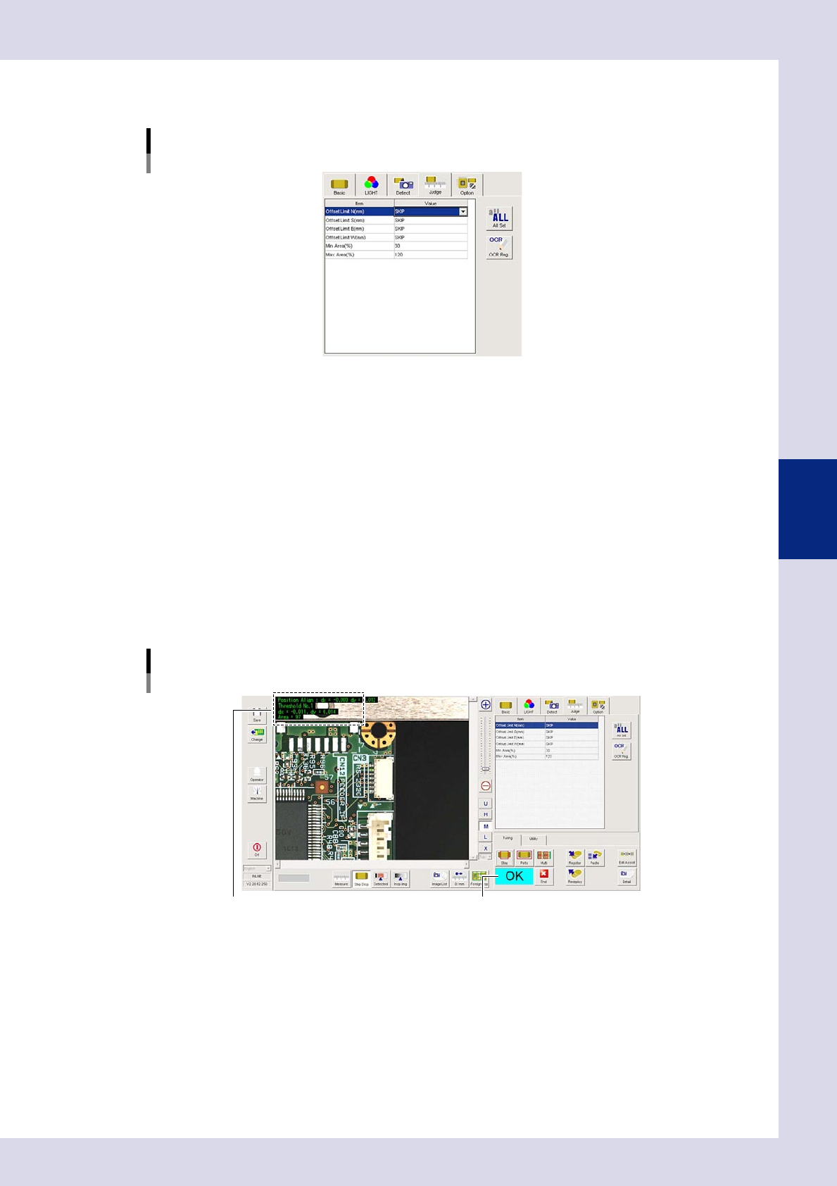
Set the "Judge" parameters.
Open the "Judge" tab and set the following parameters.
"Judge" parameters
Status: Solder Quantity Check
24421-P6-00
Offset Limit N - W (mm)
These are not normally used and should be set to "SKIP".
Min Area (%)
If the ratio of the detected area to the standard area is smaller than the value set here, then an NG
occurs.
Ref. value 30%
Max Area (%)
An NG result is judged if the ratio relative to the standard area for the detected area exceeds this
value.
Ref. value 120%
4
Perform a step test.
1. Press the [Step] button at the "Tuning" tab to perform a test for the created step.
2. Take a note of and check the detection data, and then press the [End] button.
Screen after a step test is finished
Test resultDisplays detected data.
24422-P6-00
Detected data
dx =, dy = : Amount that the step frame center deviates from the detection area center
Threshold No. : Threshold No. used for inspection
Area = : Percentage of the detected area relative to the standard area
3. If the test result is not judged correctly, review all parameters while referring to the detection data.