YSI_Prog_E - 第180页
4-20 4 Inspection status 3 Set the "Judge" par ameters. Open the "Judge" tab and set the following param eters. "Judge" parameters Status: Position Correction 24429-P6-00 Position Correct Li…
4-19
4
Inspection status
1.7 Position Correction
In addition to the usual position corrections based on board fiducial marks, this inspection mode corrects the
inspection positions. The inspection step positions specified for the parts are offset by an amount equal to the
recognized positional displacement. By performing fiducial mark position correction, the inspection step
position of specified steps can be offset by an amount equal to the mark positional displacement.
1
Make a "step" setting.
1. Create a step frame.
2. Open the "Basic" tab, and set the "Status" in the basic parameters to "Position Correction".
3. Open the "LIGHT" tab, and set the lighting parameters as "sampling light type" and "threshold value".
Sampling light type reference: Luminance
Status (inspection mode)
Position Correction
Set to "Position Correction".
Step frame
24427-P6-00
2
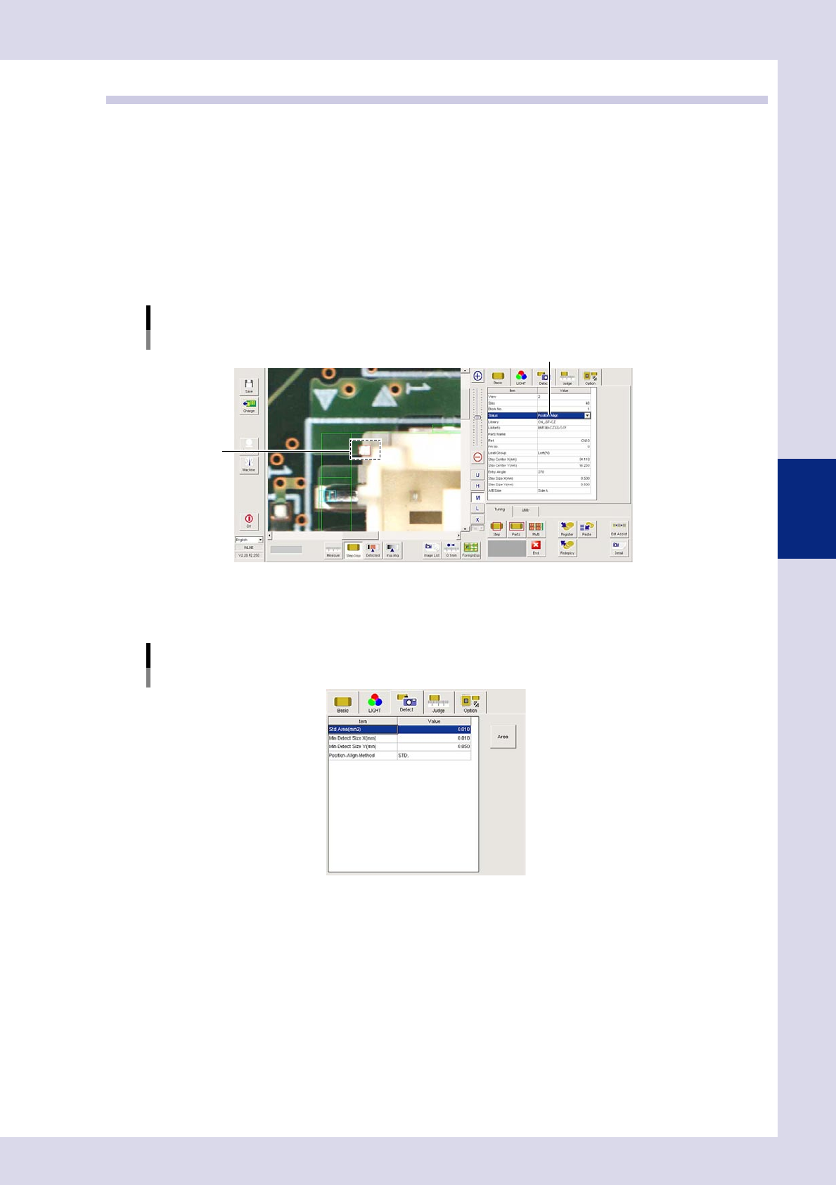
Set the "Detect" parameters.
Open the "Detect" tab and set the following parameters.
"Detect" parameters
Status: Position Correction
24428-P6-00
Minimum Detectable Size X, Y (mm)
Set the minimum inspection object size.
Enter a small value (X, Y = approx. 0.01 mm) at first. (An appropriate value is set at Step 6.)
4-20
4
Inspection status
3
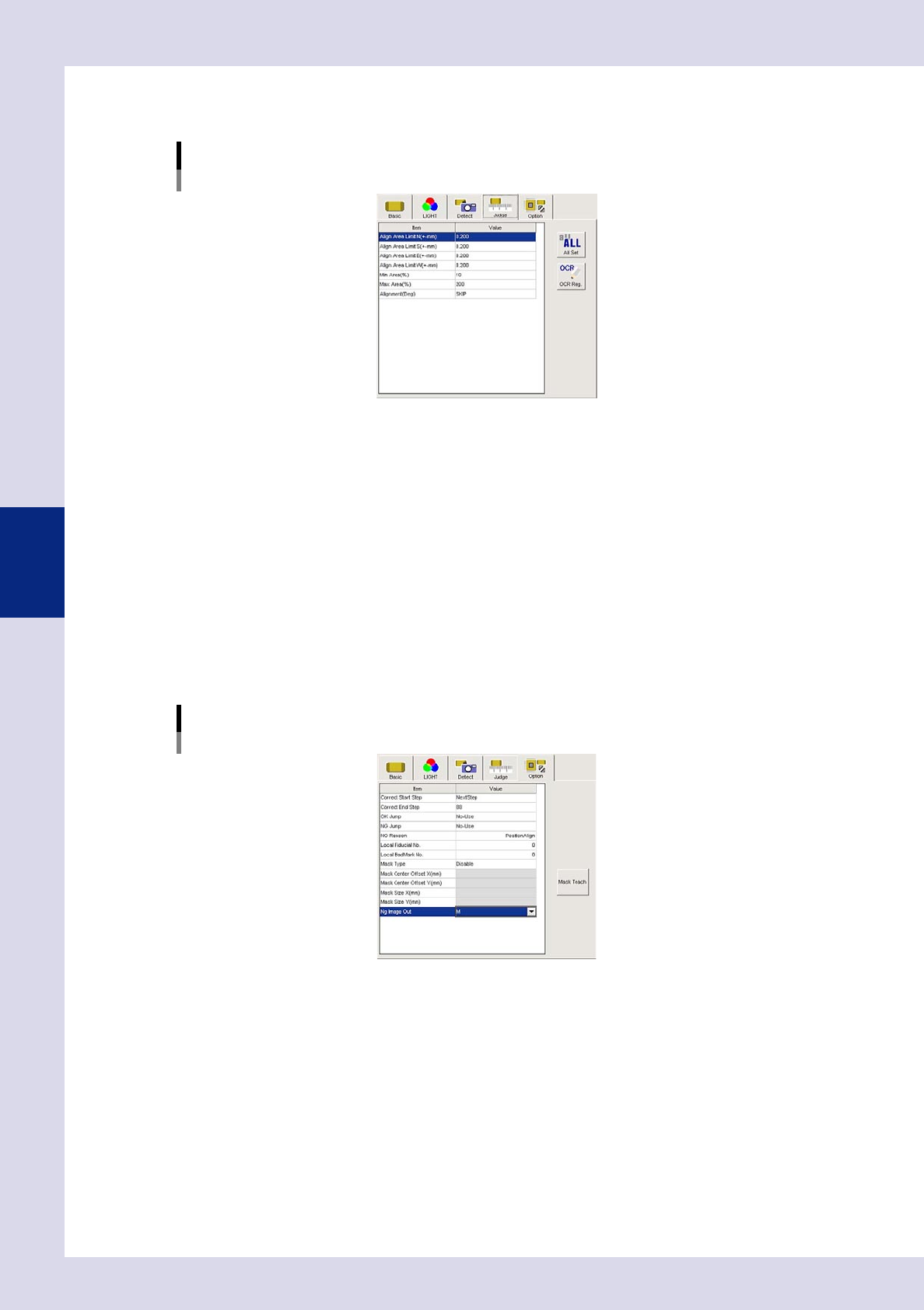
Set the "Judge" parameters.
Open the "Judge" tab and set the following parameters.
"Judge" parameters
Status: Position Correction
24429-P6-00
Position Correct Limit N - W (mm)
Set the limit amount for position correction.
If the detection position (amount of displacement) exceeds the limit, an NG result is judged, and
position correction is not performed. Set the direction to "SKIP" if not using it as a reference.
Min Area (%)
Sets the minimum area for the area standard. An NG result is judged if less than this value.
Ref. value 10%
Max Area (%)
Sets the maximum area for the area standard. An NG result is judged if less than this value.
Ref. value 200%
4
Set the "Option" parameters.
Open the "Option" tab and set the following parameters.
"Option" parameters
Status: Position Correction
Correct Start Step
The number of the first step for which position correction is performed can be selected from a drop-
down list or entered.
Correct End Step
The number of the last step for which position correction is performed can be selected from a drop-
down list or entered.
24430-P6-00
4-21
4
Inspection status
5
Perform a step test.
1. Press the [Step] button at the "Tuning" tab to perform a test for the created step.
2. When the test result appears, press the [End] button. When doing so, there is no problem if the test
result is "NG".
6
Press the [Detail] button.
The "Inspect result" dialog box opens. Press the [Auto Calculation] button. The following items in the
detection conditions parameters are set automatically.
Minimum Detectable Size X
The minimum X and Y widths for the inspection object are set.
7
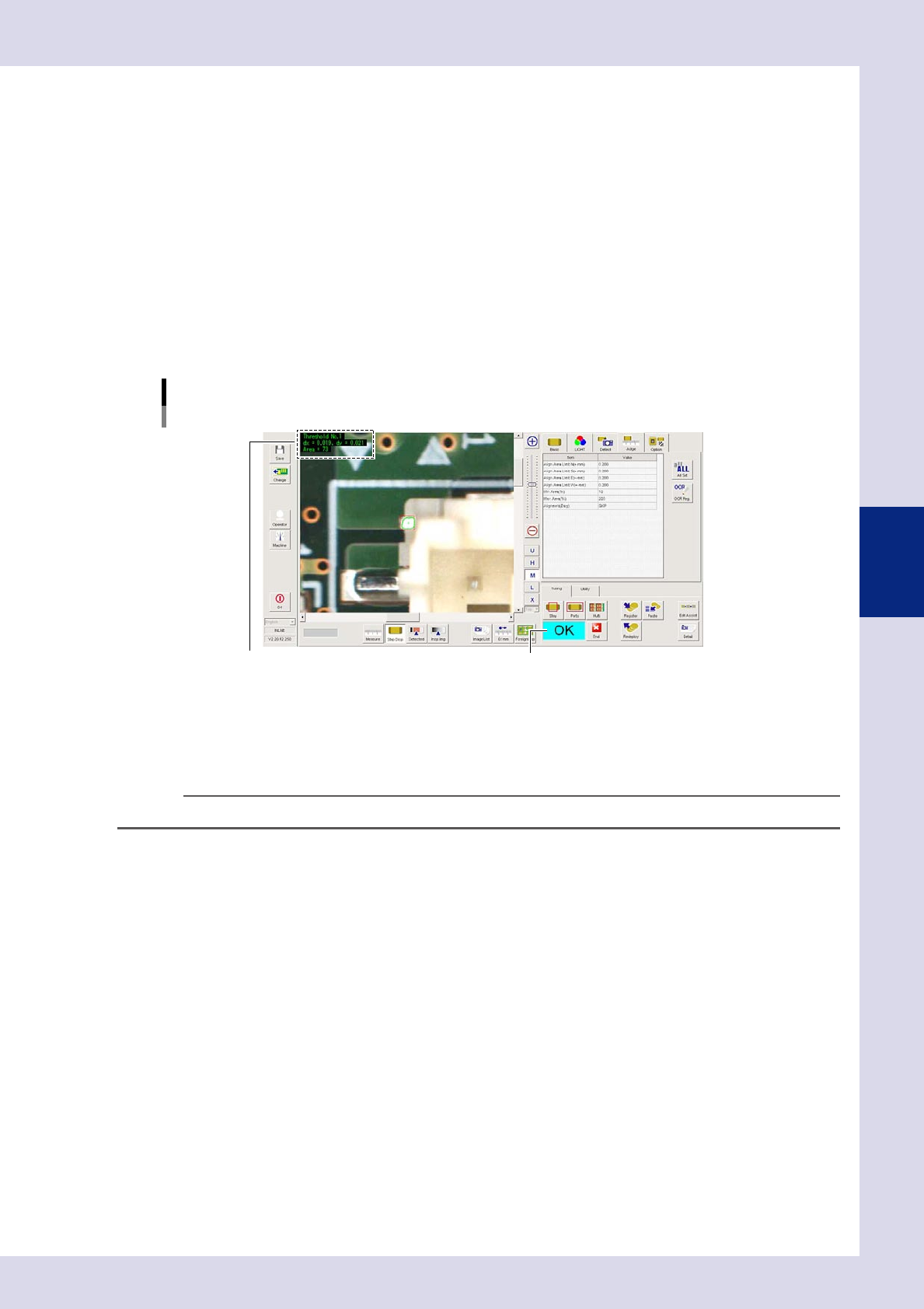
Perform a step test again.
1. Press the [Step] button at the "Tuning" tab again to perform a step test.
2. Take a note of and check the detection data, and then press the [End] button.
Screen after a step test is finished
Test resultDisplays detected data.
24431-P6-00
Detected data
Threshold No. : Threshold No. used for inspection
dx =, dy = : Amount that the step frame center deviates from the detection area center
Area = : Percentage of the detected area relative to the standard area
TIP
If dx and dy are "0", this means than the position correction limit is exceeded, so the position is not offset.
3. If the test result is not judged correctly, review all parameters while referring to the detection data.