YSI_Prog_E - 第188页
4-28 4 Inspection status 1.10 Shape Check Use this inspection mode to inspect the shapes of inspection objects. T his description takes an aspect ratio comparison as an example. 1 Make a "step" setting. 1. Crea…

4-27
4
Inspection status
7
Set the basic parameters and judgment conditions parameters.
1. Open the "Basic" tab, and set the "Status" in the basic parameters to "Comparison".
2. Open the "Judge" tab and set the following items.
"Judge" parameters
Status: Comparison
24440-P6-00
Memory No1
Select memory No. "1" set at Step 2.
Memory No2
Select memory No. "2" set at Step 5.
TIP
Inspection is performed at comparison steps with difference in luminance obtained by subtracting the "Memory No2"
luminance from "Memory No1" luminance.
Target of Compare
Luminance
Performs a comparison with the difference in the luminance measurement results for steps set at the
memory No. settings.
Thickness (YSI-X)
Performs a comparison with the difference in the thickness measurement results for steps set at the
memory No. settings.
8
Perform a "step" test.
1. Press the [Step] button to perform a test for the created step. Test results and detection data are
displayed when testing is complete. When doing so, there is no problem if the test result is "NG".
Detection data
Difference =: This is the difference in luminance between two measured steps.
2. Take a note of and check the detection data, and then press the [End] button.
9
Set the "Min Area" and "Max Area" in the "Judge" parameters.
Set by referring to the inspection data Difference.
Minimum
Enter approximately 80% of the Difference. An NG result is judged if the difference in luminance is less
than this value.
Maximum
Enter approximately 120% of the Difference. An NG result is judged if the difference in luminance is
greater than this value.
0
Perform a step test again.
1. Press the [Step] button at the "Tuning" tab again to perform a step test.
2. Take a note of and check the detection data, and then press the [End] button.
3. If the test result is not judged correctly, review all parameters while referring to the detection data.
4-28
4
Inspection status
1.10 Shape Check
Use this inspection mode to inspect the shapes of inspection objects. This description takes an aspect ratio
comparison as an example.
1
Make a "step" setting.
1. Create a step frame.
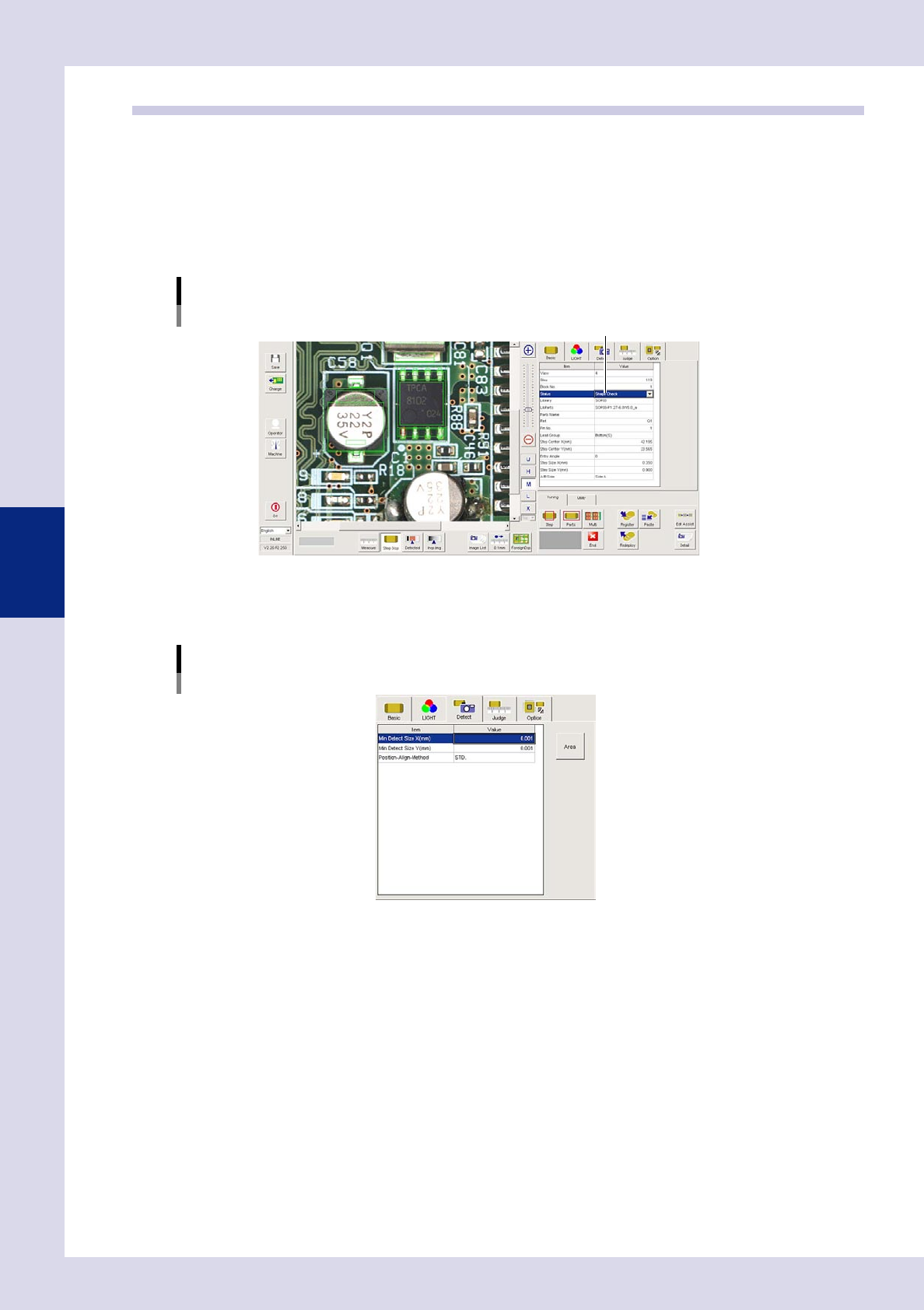
2. Open the "Basic" tab, and set the "Status" in the basic parameters to "Shape Check".
3. Open the "LIGHT" tab, and set the lighting parameters as "sampling light type" and "threshold value".
Status (Inspection mode)
Shape Check
Set to "Shape Check".
24441-P6-00
2
Set the "Detect" parameters.
Open the "Detect" tab and set the following parameters.
"Detect" parameters
Status: Shape Check
24442-P6-00
Minimum Detectable Size X, Y (mm)
Set the minimum size that can be recognized as an inspection object.
Enter a small value (X, Y = approx. 0.01 mm) at first. (An appropriate value is set at Step 6.)
4-29
4
Inspection status
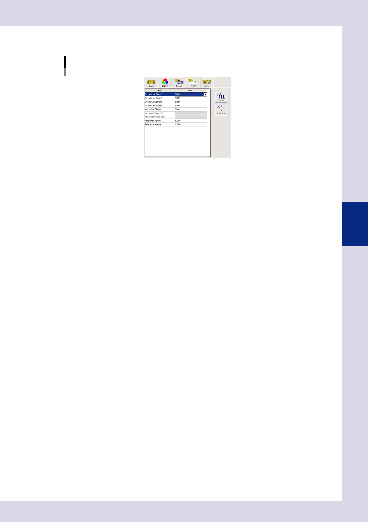
3
Set the "Judge" parameters.
Open the "Judge" tab and set the following parameters.
"Judge" parameters
Status: Shape Check
24443-P6-00
Offset Limit N, S, E, W (mm)
Set the permissible position deviation range. If not inspecting the position deviation, set all of these to
"SKIP".
Inspection Shape
Select the shape to be inspected from the following four types. "Aspect Ratio" is selected here.
Size : Performs an inspection by comparing step size and detected step size.
Circularity : Inspects the roundness of round parts.
Convexity : Inspects the degree of smoothness.
Aspect Ratio : Inspects the percentage of the detection object vertical length relative to the
horizontal length (horizontal = 100%).
Min, Max Match Ratio (%)
This setting is valid when other than "Size" is selected for "Inspection Shape". Sets the match ratio for the
inspection object shape standard. For example, if "Inspection Shape" is set to "Aspect ratio", in the
example in the drawing at Step 1, the vertical length is approximately twice the horizontal length, and
therefore the "Min Match Ratio (%)" is set to "170%", and the "Max Match Ratio (%)" is set to "230%". (Set
an appropriate value set Step 5.)
Tolerance X, Y (mm)
This setting is valid when "Size" is selected for "Inspection Shape". An OK result is judged if the recognized
step lies inside the step size dimensional tolerance.