YSI_Prog_E - 第190页
4-30 4 Inspection status 4 Perform a "step" test. 1. Press the [Step] button at the "T uning" tab to per form a test for the created step. T est results and detection data are displayed when testing i…
4-29
4
Inspection status
3
Set the "Judge" parameters.
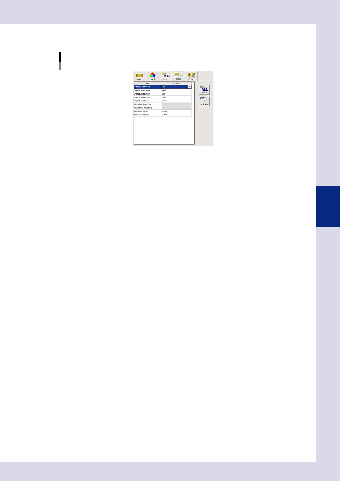
Open the "Judge" tab and set the following parameters.
"Judge" parameters
Status: Shape Check
24443-P6-00
Offset Limit N, S, E, W (mm)
Set the permissible position deviation range. If not inspecting the position deviation, set all of these to
"SKIP".
Inspection Shape
Select the shape to be inspected from the following four types. "Aspect Ratio" is selected here.
Size : Performs an inspection by comparing step size and detected step size.
Circularity : Inspects the roundness of round parts.
Convexity : Inspects the degree of smoothness.
Aspect Ratio : Inspects the percentage of the detection object vertical length relative to the
horizontal length (horizontal = 100%).
Min, Max Match Ratio (%)
This setting is valid when other than "Size" is selected for "Inspection Shape". Sets the match ratio for the
inspection object shape standard. For example, if "Inspection Shape" is set to "Aspect ratio", in the
example in the drawing at Step 1, the vertical length is approximately twice the horizontal length, and
therefore the "Min Match Ratio (%)" is set to "170%", and the "Max Match Ratio (%)" is set to "230%". (Set
an appropriate value set Step 5.)
Tolerance X, Y (mm)
This setting is valid when "Size" is selected for "Inspection Shape". An OK result is judged if the recognized
step lies inside the step size dimensional tolerance.
4-30
4
Inspection status
4
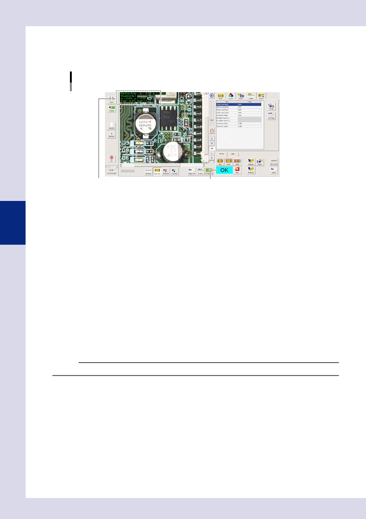
Perform a "step" test.
1. Press the [Step] button at the "Tuning" tab to perform a test for the created step.
Test results and detection data are displayed when testing is complete. When doing so, there is no
problem if the test result is "NG".
Screen after a step test is finished
Test resultDisplays detected data.
24444-P6-00
Detection data
Threshold No .: This is the threshold No. applied to inspection.
dX=, dY= : This the amount of displacement between the step frame and center of the
detection area.
Aspect Ratio= : This is a ratio based on the inspection shape.
2. Take a note of and check the detection data, and then press the [End] button.
5
Set the "Min Match Ratio" and "Max Match Ratio" in the "Judge" parameters.
Min Match Ratio (%)
Enter a value approximately 80% of the inspection data Aspect Ratio.
Max Match Ratio (%)
Enter a value approximately 120% of the inspection data Aspect Ratio.
6
Set the Min Detect Size X, Y (mm) for the detection conditions parameters.
1. Press the [Detail] button to display the "Test Results" screen.
2. Take a note of the test results maximum X width and maximum Y width values, and then press the
[Close] button to close the screen.
3. Set a value approximately 70% of the maximum X width for "Min Detect Size X (mm)" in the detection
conditions parameters, and set a value approximately 70% of the maximum Y width for "Min Detect
Size Y (mm)".
TIP
The inspection object is the largest shape within the step frame. The [Auto Calculation] button is disabled.
7
Perform a step test again.
1. Press the [Step] button at the "Tuning" tab again to perform a step test.
2. Take a note of and check the detection data, and then press the [End] button.
3. If the test result is not judged correctly, review all parameters while referring to the detection data.
4-31
4
Inspection status
1.11 Code Recognition
This inspection status is used to read QR Codes and so on affixed to boards to identify boards IDs. The board
ID is the file name used when outputting SPC data, and when outputting results to the Repair Station (option).
n
NOTE
If using this inspection status for a newly created inspection program, set at the [Data Edit] - "CodeScan" tab.
1
Create a "step" for code recognition.
Create the first step in the inspection program for code recognition.
1. Create a step frame.
2. Open the "Basic" tab, and set the "Status" in the basic parameters to "Code Recognition".
Status (inspection mode)
Code Recognition
Set to "Code Recognition".
24445-P6-00
2
Set the "LIGHT" parameters.
1. Open the "LIGHT" tab and select "Luminance" at "Light Sampling Type".
2. Press the button to the right of the sampling light value field to open the sampling light list, select
"Mb+Lb" from the list, and then press the [OK] button.
3
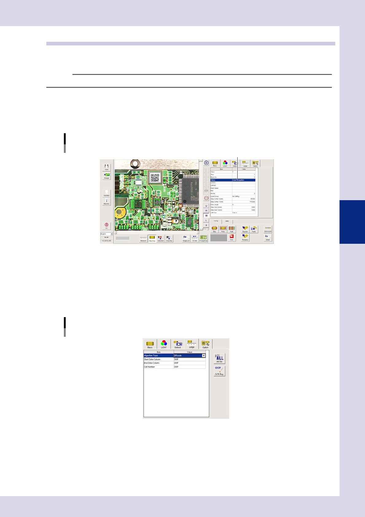
Set the "Judge" parameters.
Open the "Judge" tab and set the following parameters.
"Judge" parameters
Status: Code Recognition
24446-P6-00