YSI_Prog_E - 第192页
4-32 4 Inspection status Algorithm T ype Select the object to be inspected from the following three types. QRcode : Select to recogni ze QRcode. D-matrix : Select to recognize Data matrix. Barcode : Select to recognize b…
4-31
4
Inspection status
1.11 Code Recognition
This inspection status is used to read QR Codes and so on affixed to boards to identify boards IDs. The board
ID is the file name used when outputting SPC data, and when outputting results to the Repair Station (option).
n
NOTE
If using this inspection status for a newly created inspection program, set at the [Data Edit] - "CodeScan" tab.
1
Create a "step" for code recognition.
Create the first step in the inspection program for code recognition.
1. Create a step frame.
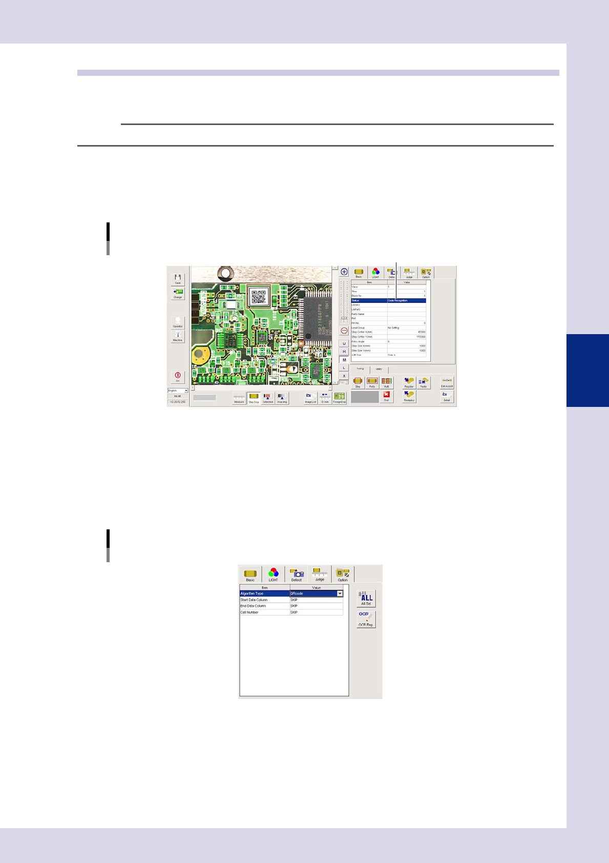
2. Open the "Basic" tab, and set the "Status" in the basic parameters to "Code Recognition".
Status (inspection mode)
Code Recognition
Set to "Code Recognition".
24445-P6-00
2
Set the "LIGHT" parameters.
1. Open the "LIGHT" tab and select "Luminance" at "Light Sampling Type".
2. Press the button to the right of the sampling light value field to open the sampling light list, select
"Mb+Lb" from the list, and then press the [OK] button.
3
Set the "Judge" parameters.
Open the "Judge" tab and set the following parameters.
"Judge" parameters
Status: Code Recognition
24446-P6-00
4-32
4
Inspection status
Algorithm Type
Select the object to be inspected from the following three types.
QRcode : Select to recognize QRcode.
D-matrix : Select to recognize Data matrix.
Barcode : Select to recognize barcodes.
Start Data Column
Enter the start row for acquiring the recognized codes as data.
End Data Column
Enter the end row for acquiring the recognized codes as data.
Cell Number
Select the code size if "QRcode" or "D-matriX" is selected for the algorithm type.
4
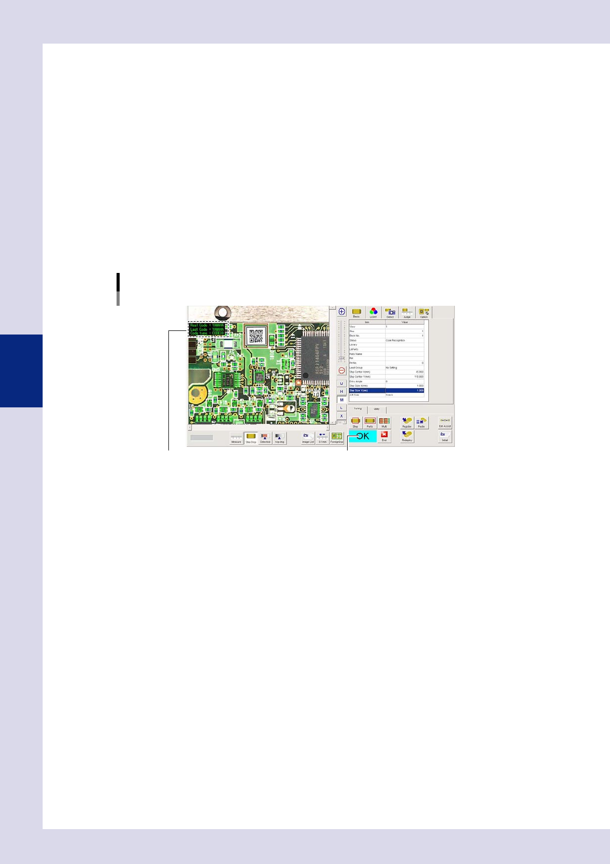
Perform a step test.
1. Press the [Step] button to perform a test for the created step. Test results and detection data are
displayed when testing is complete.
Screen after a step test is finished
Test resultDisplays detected data.
24447-P6-00
Detection data
Code : This is the recognized code characters.
2. Take a note of and check the detection data, and then press the [End] button.
3. If the test result is not judged correctly, review all parameters while referring to the detection data.
4-33
4
Inspection status
1.12 Foreign object check
This inspection status is used to detect foreign objects such as solder balls.
1
Make a "step" setting.
1. Create a step frame.
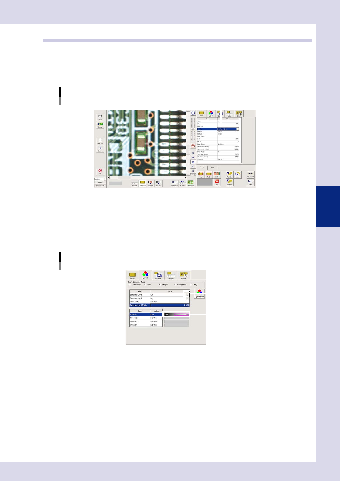
2. Open the "Basic" tab, and set the "Status" in the basic parameters to "Foreign object".
Status (inspection mode)
Foreign Object
Set to "Foreign Object".
24448-P6-00
2
Set the "LIGHT" parameters.
1. Open the "LIGHT" tab and select "Luminance" at "Light Sampling Type".
2. Press the button to the right of the sampling light value field to open the sampling light list, select
"Lb" from the list, and then press the [OK] button.
3. Set "Use" for "Thresh 1", and use the threshold slide bar to set the lower limit to 100, and upper limit to
255.
"LIGHT" parameters
Status: Foreign Object
Opens a lighting list.
Set the upper and lower threshold values.
24449-P6-00
4. Press the [Detected] button in the button area, and verify that only solder balls or foreign objects are
red in the field-of-view screen. If only the target object fails to turn red, correct the sampling light or
threshold value.