YSI_Prog_E - 第195页
4-35 4 Inspection status 5 Perform a step test. 1. Press the [Step] button to per form a test for the created step. T est results and detection data are displayed when testing is complete. Screen after a step test is fin…
4-34
4
Inspection status
3
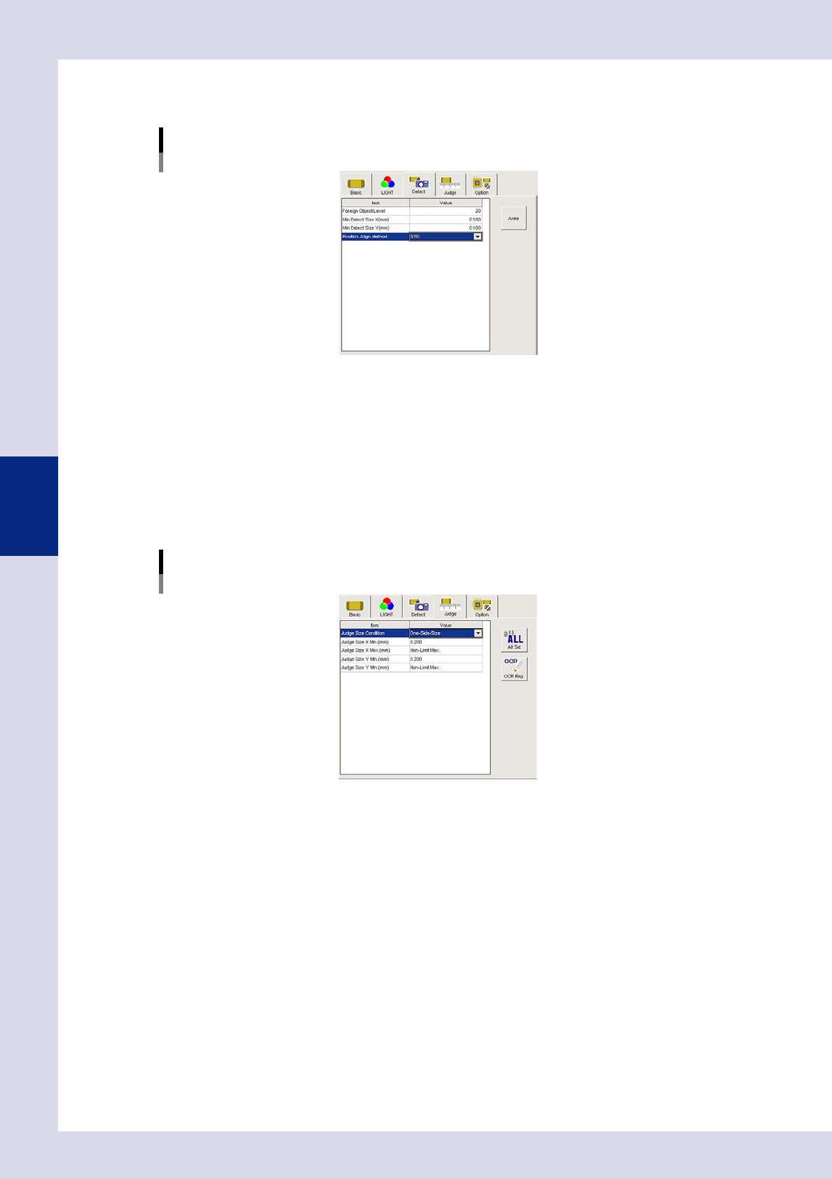
Set the "Detect" parameters.
Open the "Detect" tab and set the following parameters.
"Detect" parameters
Status: Foreign Object
24450-P6-00
Foreign Object Level
Set the difference in luminance level between objects to be detected as a foreign object and its
surroundings to a value from 0 to 255. Set to "20" at first.
Minimum Detectable Size X, Y (mm)
Enter the minimum detection size X and Y for objects to be detected as the target object. Set to a value
of approximately "0.1" at first.
4
Set the "Judge" parameters.
Open the "Judge" tab and set the following parameters.
"Judge" parameters
Status: Foreign Object
24451-P6-00
Judge Size Condition
Set whether to judge as an NG result if both the X and Y sizes of the detected foreign object are judged
to be NG, or to judge as an NG result when even one of the X or Y sizes is judged to be NG when
judging foreign object inspection.
Judge Size X Min. (mm)
An OK result is judged if the X direction size of the detected foreign object is less than this value.
Judge Size X Max. (mm)
An OK result is judged if the X direction size of the detected foreign object is greater than this value.
Judge Size Y Min. (mm)
An OK result is judged if the Y direction size of the detected foreign object is less than this value.
Judge Size Y Max. (mm)
An OK result is judged if the Y direction size of the detected foreign object is greater than this value.
4-35
4
Inspection status
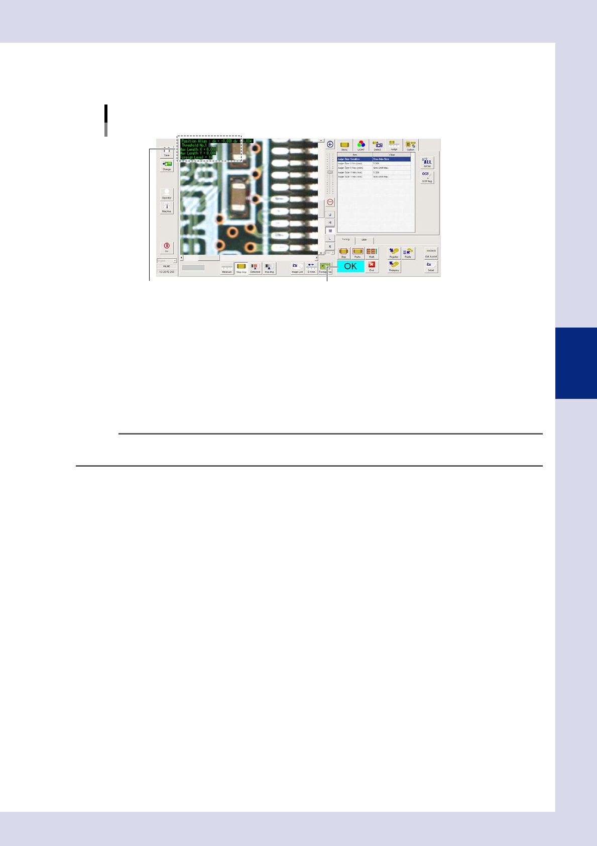
5
Perform a step test.
1. Press the [Step] button to perform a test for the created step. Test results and detection data are
displayed when testing is complete.
Screen after a step test is finished
Test resultDisplays detected data.
24452-P6-00
Detection data
Position Align dX =, dY = : These are the values corrected with position correction.
Threshold No. : This is the threshold No. applied to inspection.
MaXLength X = : This is the maximum detection width X.
MaXLength Y = : This is the maximum detection width Y.
Foreign Level = : This the maximum foreign object level.
2. Take a note of and check the detection data, and then press the [End] button.
3. If the test result is not judged correctly, review all parameters while referring to the detection data.
TIP
Foreign object check steps can be created for all views by pressing the [Edit Assist] button and selecting the "Foreign
Object" tab.
4-36
4
Inspection status
1.13 Ball joint check (YSi-X)
This inspection status is used to detect the solder ball joint status on parts such as BGAs and CSPs.
1
Make a "step" setting.
1. Create a step frame.
2. Open the "Basic" tab, and set the "Status" in the basic parameters to "Ball joint check".
Status (Inspection mode)
Boll Joint Check
Set to "Boll Joint Check".
24453-P6-00
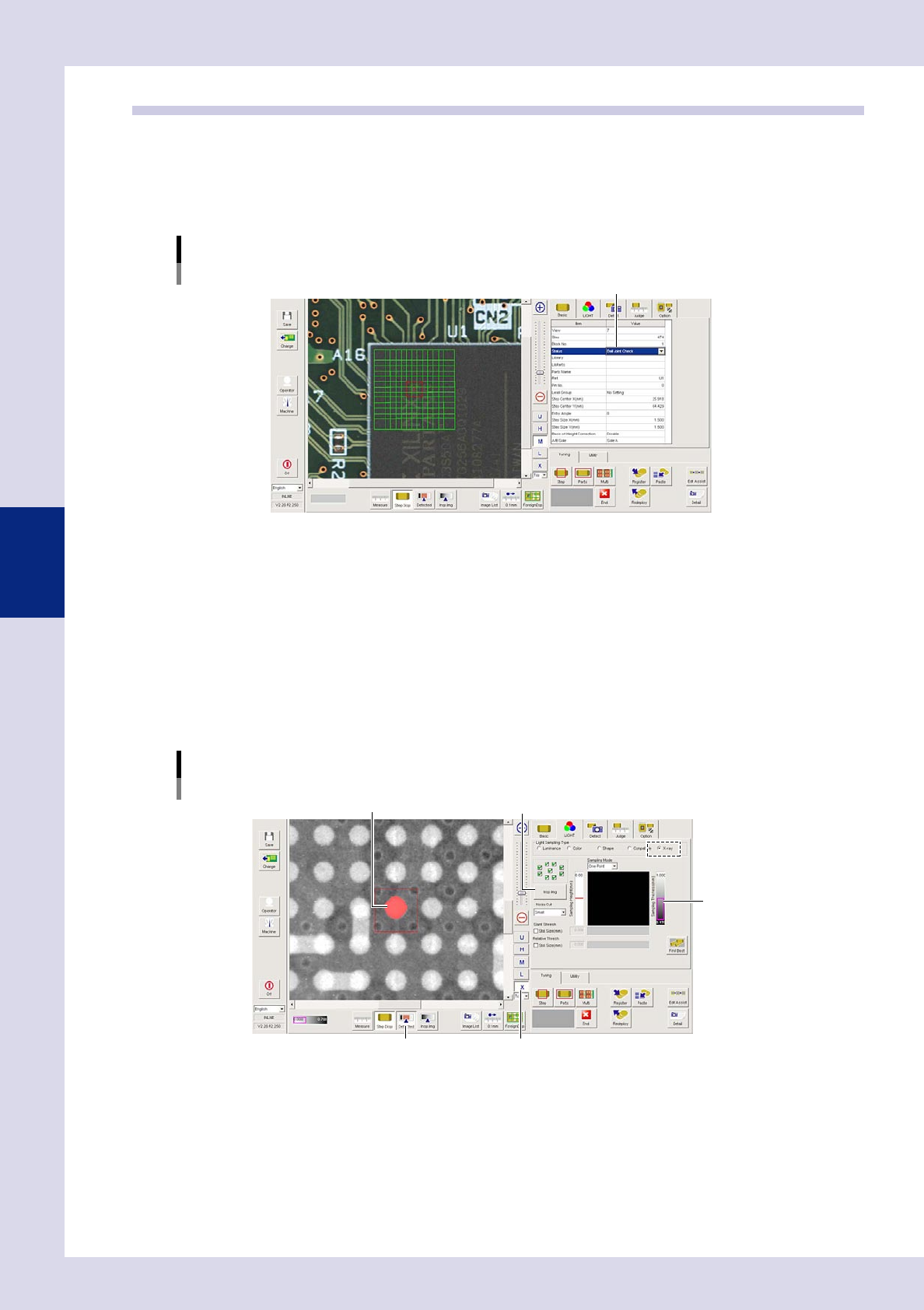
2
Set the "LIGHT" parameters.
Open the "LIGHT" tab and set the following items.
1. Select "X-ray" at "Light Sampling Type".
2. Press the [Insp. Img] button to open the "Insp. Img" screen, and select the "Custom CT" tab. Move the
fault plane height setting bar up and down to set the inspection height. Press the [OK] button at the
position where the solder in the CT image appears largest to end setting, and then close the "Insp.
Img" screen.
3. Press the [X] button to display the X-ray image.
4. Press the [Detected] button. Adjust the sampling thickness slide bar to show only solder balls in red.
Lighting parameter settings
Sampling thickness slide bar
[Insp. Img] buttonSolder ball
[X] button[Detected] button
24454-P6-00