YSI_Prog_E - 第203页
4-43 4 Inspection status Measure Method Select the method used to obtain the height meas urement value from the following four types. • Spot Measures the height at the coordinate position in the center of the ste p. • …
4-42
4
Inspection status
1.15 Height measurement (option)
This inspection status can be used if equipped with the optional laser height sensor. The height of the
inspection object is measured using the laser height sensor to check whether the result lies within the standard.
After measuring with the board surface and so on as the reference height at "Height Measure" screen, the
height of the inspection object position is measured, and the difference between the reference height is taken
as the parts height. For details, see "Laser Height Sensor" at the end of the Operator's Manual.
1
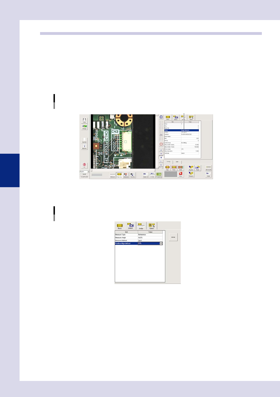
Make a "step" setting for reference height measurement.
1. Create a step frame.
2. Open the "Basic" tab, and set the "Status" in the basic parameters to "Height measure".
Status (Inspection mode)
Height Measure
Set to "Height Measure".
24463-P6-00
2
Set the "Detect" parameters.
Open the "Detect" tab and set the following parameters.
[Detect] tab
24464-P6-00
Measure Type
Select "Reference" from the drop-down list.
Measure Angle
Select the laser beam emission direction (angle) when measuring the parts height as the laser unit
rotates from a drop-down list.
If "AUTO" is selected, the laser emission direction will be the part outer direction.
4-43
4
Inspection status
Measure Method
Select the method used to obtain the height measurement value from the following four types.
• Spot
Measures the height at the coordinate position in the center of the step.
• ScanMaximum
Measures the height along the step length direction center line and takes the maximum height as
the measurement value.
• ScanMean
Measures the height along the step length direction center line and takes the average height as the
measurement value.
• ScanMinimum
Measures the height along the step length direction center line and takes the minimum height as the
measurement value.
3
Create a step frame for height measurement.
Copy and paste the reference height measurement step created at Step 1, and move it to the
measurement location.
4
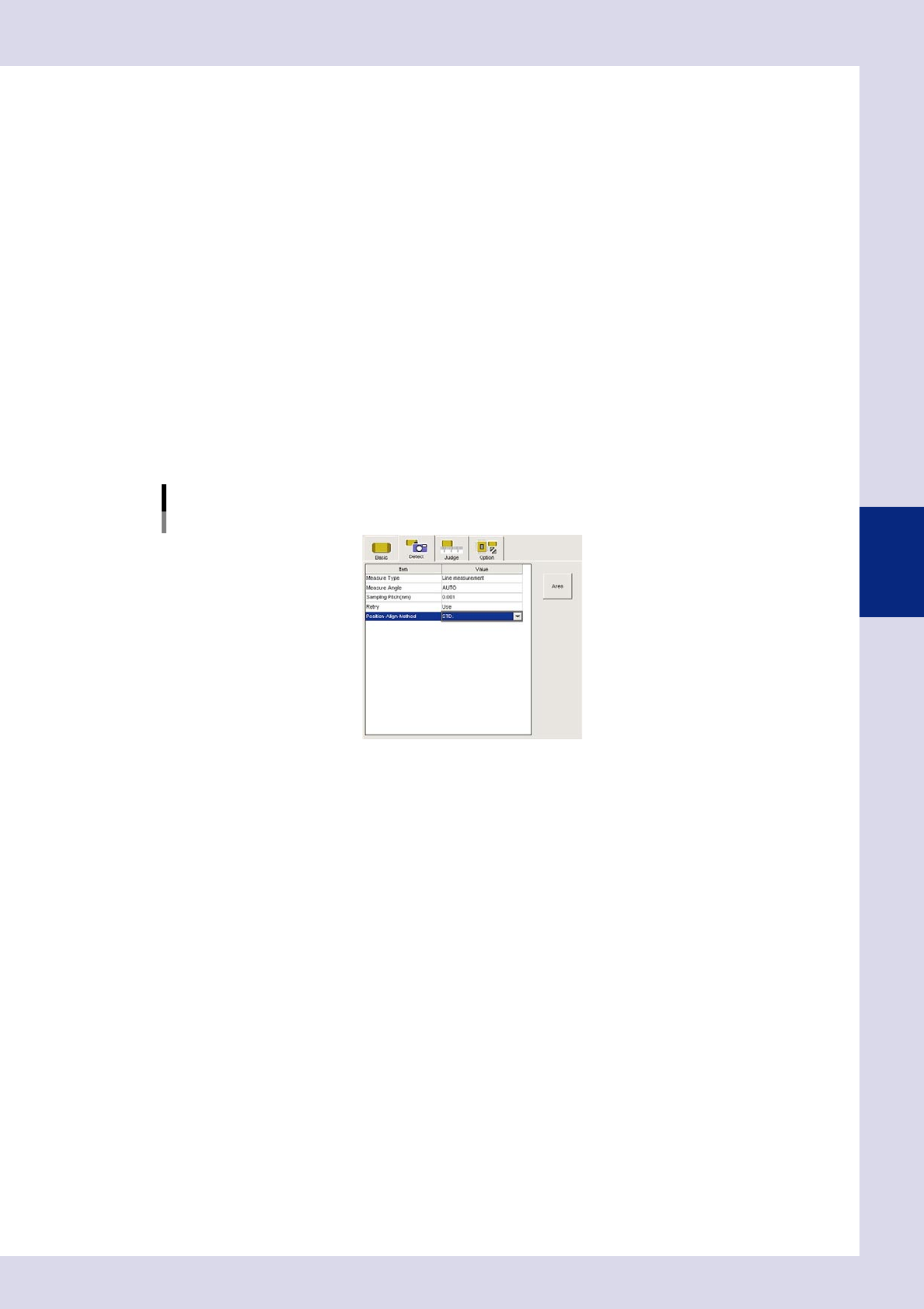
Set the "Detect" parameters.
Open the "Detect" tab and set the following parameters.
[Detect] tab
24465-P6-00
Measure Type
Select "Point measurement" or "Line measurement" from the drop-down list.
• Pointmeasurement
Measures the height at the coordinate position in the center of the step.
• Linemeasurement
Measures the height along the step length direction center line.
Sampling Pitch (mm)
This is displayed if "Line measurement" is selected for the "Measure Type". Sets the pitch at which height
measurement is performed.
Reference value: 0.001 mm
Retry
Sets whether to retry height measurement. Measurement is performed as follows if "Use" is selected.
• Ifthemeasurementtypeis"Pointmeasurement",measurementisperformedafterrotatingthehead
180°.
• Ifthemeasurementtypeis"Linemeasurement",theheadperformsmeasurementasitmovesand
returns.
4-44
4
Inspection status
5
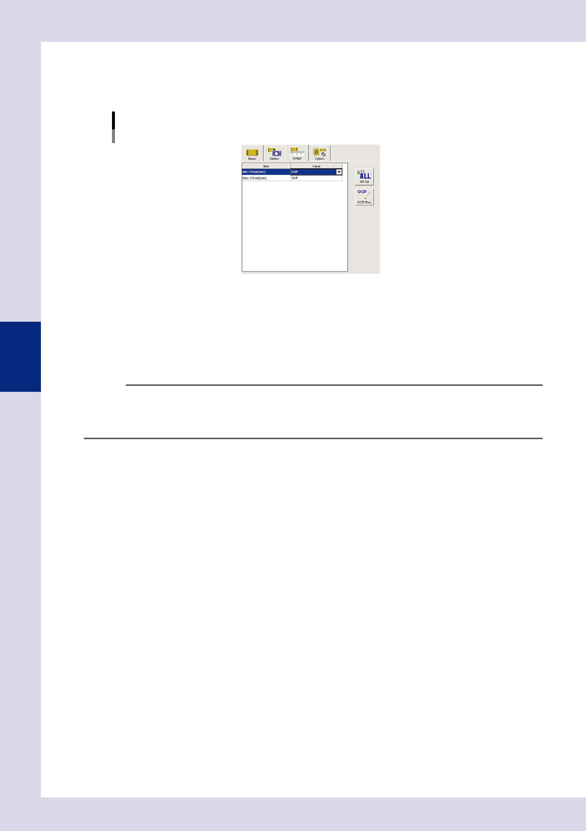
Set the "Judge" parameters.
Open the "Judge" tab, and enter the OK part height for "Min offset (mm)" and "Max offset (mm)". If the
standard has not been set, decide the minimum and maximum offset values based on the height
measurement result.
[Judge] tab
24466-P6-00
Min offset (mm)
An NG result is judged if the difference between the reference step reference height and point or line
measurement height is less than this value. Judgment is not made if set to "SKIP".
Max offset (mm)
An NG result is judged if the difference between the reference step reference height and point or line
measurement height is greater than this value. Judgment is not made if set to "SKIP".
n
NOTE
If height measurement is continued using the same reference height, copy and paste the step, and move it to the
height measurement location. The height reference will always be the previous height reference measurement step. If
the reference height measurement step position and height measurement step position are at a distance from one
another, measurement may be affected by board warp.
6
Perform a height measurement step test.
1. Select the height measurement step, and press the [Step] button to perform a step test. Test results
and detection data are displayed when testing is complete.
2. Take a note of and check the detection data, and then press the [End] button.
3. Refer to the detection data and review all parameters.
7
Perform a step test again.
If the test result is judged incorrectly, review all parameters.