YSI_Prog_E - 第220页
5-15 5 Inspection machine settings 2.6 Editing signal tower settings T his section describes how to specify signal tower displa y settings for all machine statuses. Settings are specified for the first lamp to the third …
5-14
5
Inspection machine settings
2.5 Library settings
Specifies settings relating to parts libraries.
"Machine settings" screen
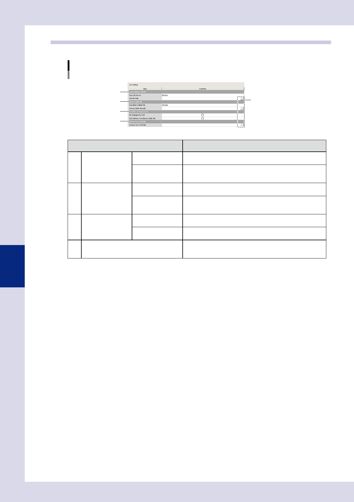
"Setting" m "Machine Information" m "Lib Setting"
1
3
2
4
[Path setting] buttons
24515-P6-00
Item Details
1 Load setting of library Use Lib Server
Select "Use" if setting the library save destination to a location other
than the "Machine" folder.
Server Path
Displays the library save location when "Use" is selected for "Use
Lib Server". If wishing to change the save location or settings, press
the path setting button on the right.
2 Library table file Use library table file
If using a library table to tie together mounter parts names and Lib
parts name when converting data, select "Use".
Library table file path
Displays the library table save location referenced when "Use" is
selected for "Use library table file". If wishing to change the save
location or settings, press the path setting button on the right.
3
Condition of
Deployment
No changes to OCR
By selecting this check box, the inspection character string for
character recognition when deploying libraries is not changed.
Set LibParts from
library table file
Deploys Lib parts name from the library table when deploying
libraries.
4 Library Text Out Path
Displays the data save destination when text output button is
pressed at the library details screen. If wishing to change the save
location or settings, press the path setting button on the right.
5-15
5
Inspection machine settings
2.6 Editing signal tower settings
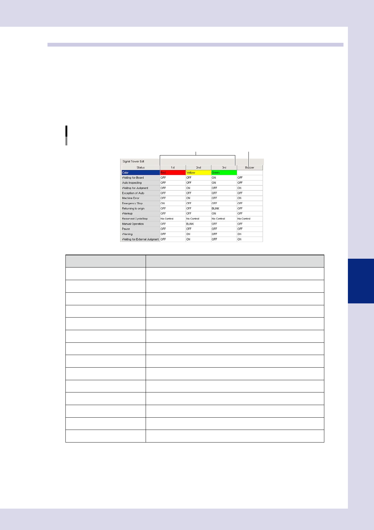
This section describes how to specify signal tower display settings for all machine statuses. Settings are
specified for the first lamp to the third lamp. (The signal tower lamps are arranged in order first lamp, second
lamp, third lamp, from top to bottom.)
Signal tower display settings
Signal tower display settings are specified for all machine statuses. "No Control", "OFF", "BLINK", or "ON" can be set for
each lamp. Refer to the following table for details on the items that can be set.
Buzzer settings
Buzzer ON/OFF settings are specified for all machine statuses.
"Machine settings" screen
"Setting" m "Machine Information" m "Signal Tower Edit"
Signal tower display settings Buzzer setting
24516-P6-00
Item Status
Color Lamp color display
Waiting for Board Waiting for board loading
Auto inspecting During automatic inspection
Waiting for Judgment Waiting for judgment from secondary judgment, semi-auto screen
Exception of Auto Other than automatic inspection
Machine Error During machine error
Emergency Stop Emergency stop condition
Returning to origin Returning to origin
Warmup Performing a warmup
Reserved CycleStop Awaiting cycle stop
Manual Operation During manual operation
Pause Operation paused
Warning During machine warning
Waiting for External Judgment Waiting for judgment from Remote Judgment Station (option)
5-16
5
Inspection machine settings
2.7 Data conversion settings
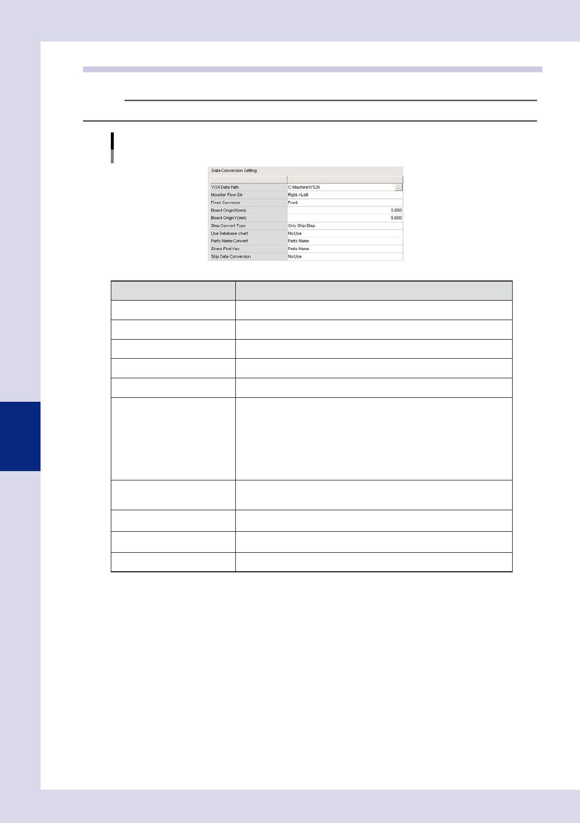
Specifies detailed settings when converting mount data to inspection machine data.
TIP
For details on data conversion operation, see section 2.2, "Data conversion", in Chapter 2.
"Machine settings" screen
"Setting" m "Machine Information" m "Data Conversion Setting"
24517-P6-00
Item Details
YGX Data Path Specifies the folder in which the YGX data to be converted is saved.
Mounter Flow Dir Selects the mounter flow direction.
Fixed Conveyor Selects the mounter fixed side conveyor.
Board OriginX(mm) Enter the board origin X coordinate to be converted.
Board OriginY(mm) Enter the board origin Y coordinate to be converted.
Step Convert Type
Selects the step conversion type from the following.
• Only Skip Step
Only reference steps for the parts exterior size are created.
• Inspection Step
Reference steps and parts check steps for the parts exterior size (some steps
will also be OK) are created.
• Inspection + Visual Step"
Reference steps and parts check steps for the parts exterior size (all steps will
be NG) are created.
Use Database chart
If set to "Use", the library parts names set in the library table are set for the step
library parts names when converting data. If set to "No Use", library parts names
are not set when converting data.
Parts Name Convert
Specifies whether to set the YGX data "Parts Name" or "Comment" as the
inspection data parts name when converting data.
Sharp Find Key
Specifies whether to set the library table "Parts Name" or "Comment" as the
inspection data parts name when converting data.
Skip Data Conversion Sets whether to convert parts skipped in YGX data to inspection machine data.