YSI_Prog_E - 第224页
S-1 I INDEX A All Set button 3-8 Analysis button 3-26 Area button 3-5 Auto Calculation button 3-27 Auto creation function buttons 2-31 Auto inspection screen 1-13 Back fillet 2-8 Bad mark function 2-24 Bad Mark scr…
i
Appendix
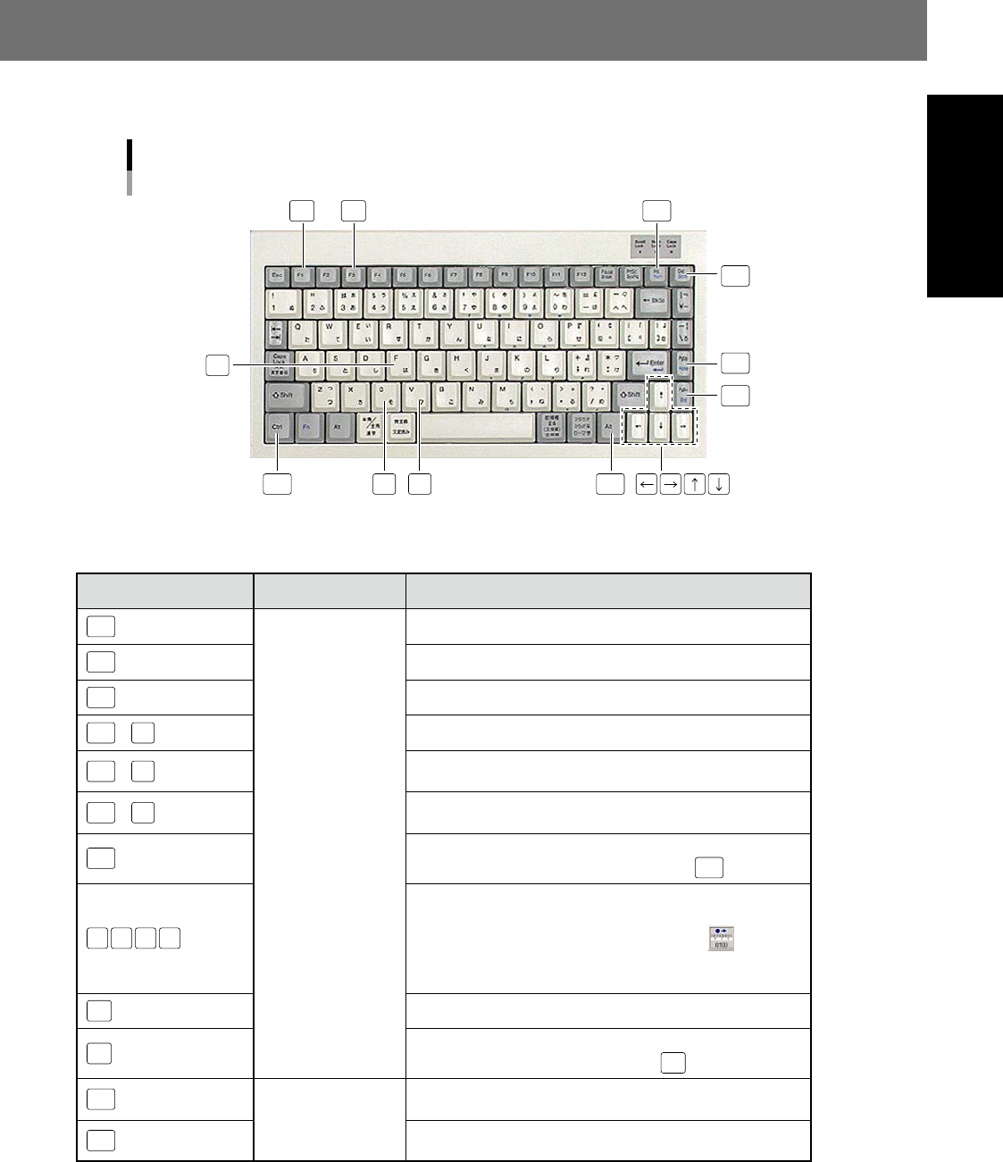
1. List of keyboard shortcut keys
The following shortcut keys can be used at the [Data Edit] - "Step" screen or NG monitor screen, and at the
second judgment screen.
List of shortcut key functions
Del
Del
Ins
VC
Home
F
End
Ctrl
F1
F3
23002-P6-00
n
Shortcut function list
Shortcut keys Applicable screen Function
Home
[Data Edit] - [Step]
screen
Moves the cursor to the first step in the selected view.
End
Moves the cursor to the last step in the selected view.
Del
Deletes the selected (red, thick-bordered rectangle) step.
Ctrl
+
F
Displays a step search dialog box.
Ctrl
+
C
Copies the selected (red, thick-bordered rectangle) step to the
clipboard.
Ctrl
+
V
Inserts the step data copied to the clipboard after the selected
(red, thick-bordered rectangle) step.
Ctrl
+
Adds and selects individual steps. Selected steps are
unselected by clicking while holding down the
Ctrl
button.
← → ↑ ↓
Moves the selected (red, thick-bordered rectangle) step in the
arrow direction.
The movement pitch is changed by pressing the
button.
If a step that can be edited is not selected, the selection cursor
moves on to the previous or next step.
F1
Selects steps with same Ref. No.
F3
Displays steps that have not been set in the library. Displays
the next unset step when pressed again
F3
.
Ins
NG monitor screen,
YSi-S: Second
judgment screen
This is the same operation as pressing the [OK] button on the
operation screen.
Del
This is the same operation as pressing the [NG] button on the
operation screen.

S-1
I
INDEX
A
All Set button 3-8
Analysis button 3-26
Area button 3-5
Auto Calculation button 3-27
Auto creation function buttons 2-31
Auto inspection screen 1-13
Back fillet 2-8
Bad mark function 2-24
Bad Mark screen 1-6,1-16
Bad mark settings 2-26
Ball joint check 4-36
Basic parameters 2-16
Batch replacement 3-34
Board parameter 1-4
Board screen 1-4
Bridge 2-6
Brightness Level 4-22
Button area 1-1,1-2
C
Carry Log screen 1-19
CE marking i
Change 1-2
Changing registered operator details 5-4
Character Recognition 4-11
Checking libraries 2-48
Code Recognition 4-31
Code Scan screen 1-12
Color 3-13
Comparison 4-25
Conveyor screen 1-18,1-20
Conveyor transfer settings 5-11
Copying steps 3-29
Creating all views 2-31
Creating full board images 2-12
CUSTOM lighting 2-22
Data Check 1-10
Data conversion 2-10
Data conversion settings 5-16
Data Edit screen 1-4
Data Rotate 1-4
Date Edit screen 1-4
Deleting multiple views 2-35
Deploying libraries 2-46
Dummy feeder iv
E
Editing access levels 5-7
Editing Assistance 3-28
Editing groups 5-5
Editing pin Nos. 3-30
Editing signal tower settings 5-15
Electrode Check 4-5
Ending the automatic inspection 1-35
Fiducial function 2-15
Fiducial screen 1-5
Fillet 2-7
Flowchart for creating an inspection
program 2-9
Foreign object check 4-33
Foreign object check deployment 3-32
Free area 1-1
G
GROUP 5-3
H
Height Correct screen 1-11
Height measurement 4-42
Height Measure screen 1-17
History 1-24
I
Inspection complete screen 1-34
Inspection method 2-2
Inspection screen 1-13
Inspection status 4-1
Inspection with optical camera 2-5
Inspection with X-ray camera 2-8
Installation settings 5-9
I/O screen 1-22
Judge screen 1-16
K
keyboard shortcut keys i
L
Lead Check 4-16
LEVEL 5-3
Lib Non 1-10
Lib Non Set 2-38
Library details 2-50
Library settings 5-14
Light detail settings 3-16
Light Sampling Type 3-2
Luminance 3-10
Machine settings 5-8
Manual contents i
Manuals supplied with machine i
Manual view creation procedure 2-32
Mask function 3-23
Mask Teach button 3-9
Measurement results 3-27
Missing part 2-5
Multiple threshold value settings 3-12
Multi-test 3-24
N
NG monitor 1-32
OCR Reg. button 3-8
Offset Limit 3-6
Operation screen 1-1
Operator access control 5-1
OPERATOR NAME 5-3
Operator selection screen 1-25
Optical inspection 2-2
Origin 1-3,1-21
Output screen 1-15
P
Page layout iv
Parts Check 4-2
PASSWORD 5-3
Pin Information Deployment 3-28
Pin position editing 3-33
Pitch input and copy of multiple views
2-36
Pitch Rep 1-7
Polarity 2-6
Polarity Check 4-8
Position Correction 4-19
Position deviation 2-5
Program change 1-3
Program list 1-3
R
Recognition method 3-10
Registering a new operator 5-1
Registering libraries 2-44
Registering user characters 3-18
S
Safety ii
Safety message vii
Save 1-2
Saving view images 2-29,2-49
Search 3-36
Secondary judgment settings 5-12
Select 1-3
Selecting inspection programs 1-26
Selecting multiple views 2-34
Server Path 5-14
Server settings 5-13
Setup screen 1-3
Shape 3-14
Shape Check 4-28
Shift tolerance 2-5

S-2
Shortening inspection time 2-31
Solder inspection of lower surface
electrode parts 2-8
Solder Quantity Check 4-14
Special Setting 5-8
Starting automatic inspection 1-26,1-27
Starting upside down automatic
inspection 1-28
Status area 1-1
Status types 4-1
Step 2-1
Step creation procedure 2-40
Step screen 1-8
Step settings 2-38
U
Unit screen 1-20
View 2-1
View screen 1-7
View settings 2-29
Void check 4-39
W
Warning labels xi
Warranty ii
When NG detection occurs 1-32
Whole screen 1-14
Width 1-4
X
X-ray 3-15
X-ray inspection 2-4