YSI_Prog_E - 第34页
iv 4. Page layout The description below shows a typical page layout used in this manual. 2-15 2 Creating and setting data 5. Block settings A "block" is the inspection range (field-of-v…

iii
3. Contents of each chapter
This manual is comprised of the following chapters.
Chapter 1
Basic operation
This chapter explains the basic configuration of the YSi software screen.
Chapter 2
Creating inspection programs
This section describes how to create new and tune existing inspection programs.
Chapter 3
Step screen
This section describes the parameters set at the "Step" screen and the functions of each button.
Chapter 4
Inspection status
This section describes how to specify all inspection status settings.
Chapter 5
Inspection machine settings
This section describes operator management and machine settings.
Appendix
This section describes keyboard shortcut functions that are available when performing screen operation.
Index
The index at the end of this manual helps you quickly find where necessary items are explained.
iv
4. Page layout
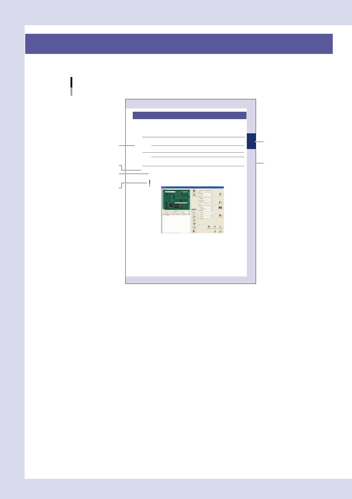
The description below shows a typical page layout used in this manual.
2-15
2
Creating and setting data
5. Block settings
A "block" is the inspection range (field-of-view) of the inspection device. Blocks must be set on the board
locations to cover all parts to be inspected. Because the image of each block is acquired and saved, block
settings must be performed on the actual machine. (On the offline software, some buttons are grayed out and
inactive.)
5.1 Basic block setting procedure
The basic block setting procedure is explained below.
NOTE
When an inspection program created with P-Tool is loaded, there is no need to set blocks because they have already
been set.
NOTE
After carefully reading the basic procedure, refer to the next section 5.2, "Block setting function details", for creating
all blocks effi ciently.
Blocks can be automatically created by using the VADMIC editor.
Open the "Data Edit" screen and set a board in place.
When you press the [Data edit] button on the "Main" screen, a "Set PCB?" message appears. At this time,
set a board at the entrance sensor detection position on the conveyor and then press the [Yes] button.
"Data Edit" screen
24219-K0-10
Step
Sub step or
description of step
Typical page layout
Chapter number
Chapter title
Figure, picture
or table caption
Note, Caution
or Warning
23001-P6-00
n
Step
This describes the procedure for each operation.
n
Substep or description of step
This provides detailed information on the steps in each procedure.
n
Figure, picture or table caption
This is the title of the figure, picture or table and appears at the upper left.
n
Note, Caution or Warning
These are explained in detail in "Safety" instructions.

Chapter 1 Basic operation
Contents
1
1
2
1.3 Setup screen 1-3
4
1.4.1 "Board" screen 1-4
1.4.2 "Fiducial" screen 1-5
1.4.3 "Bad Mark" screen 1-6
1.4.4 "View" screen 1-7
1.4.5 "Step" screen 1-8
1.4.6 "Height Correct" screen (YSi-X) 1-11
1.4.7 "Code Scan" screen 1-12
1.5 Auto inspection screen 1-13
1.5.1 "Inspection" screen 1-13
1.5.2 "Whole" screen 1-14
1.5.3 "Output" screen 1-15
1.5.4 "Bad Mark" screen 1-16
1.5.5 "Judge" screen 1-16
1.5.6 "Height Measure" screen 1-17
1.5.7 "Conveyor" screen 1-18
1.5.8 "Carry Log" screen 1-19
0
1.6.1 "Conveyor" screen 1-20
1.6.2 "I/O" screen 1-22
1.7 History 1-24
5
2. Starting and ending inspection 1-26
2.1 Starting automatic inspection 1-26
2.1.1 Selecting inspection programs 1-26
2.1.2 Starting automatic inspection 1-27
8
2.2.1 Selecting inspection programs 1-28
2.2.2 Starting automatic inspection 1-29
2.2.3 Upside down automatic inspection settings 1-30
2.3 When NG detection occurs 1-32
2.3.1 NG monitor 1-32
2.4 Inspection complete screen 1-34
2.5 Ending the automatic inspection 1-35