YSI_Prog_E - 第39页
1-4 1 asic operation 1.4 Data Edit screen T he items and buttons display ed on the "Data Edit" screen are described below . F or instructions on how to set inspection data, refer to Chapter 2, "Creating …
1-3
1
asic operation
1.3 Setup screen
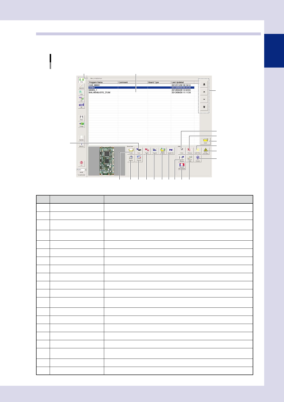
The "Setup" screen allows you to manage inspection programs and specify settings for all utilities. The items
and buttons displayed on the screen are described below.
"Setup" screen
YSi-X example
5
3
1
2
4
6
7 8 9 10
13
14
17 18
19
20
15
16
1211
24103-P6-00
Item/button name Function
1 Path Shows the path to the location where inspection programs are stored.
2 Program list Shows a list of inspection programs stored in the machine.
3 Program change
Changes the selected program in the list. Programs can also be selected by directly
clicking programs in the list.
4 Select
Loads the inspection program selected in the program list. Programs can also be loaded
by directly double-clicking programs in the list.
5 Create Press this button to create a new inspection program.
6 Copy Copies the inspection program selected in the program list.
7 Delete Deletes the inspection program selected in the program list.
8 Rename Renames the selected inspection program.
9 Board Explorer Imports or exports inspection programs.
10 Update Info. Re-creates the program list.
11 Search Searches for inspection programs.
12 Convert
Selects mount data (YGX) and converts it to an inspection program. (See Chapter 2,
"2.2 Data conversion", in this manual.)
13 Origin* Moves the inspection head, conveyor, and laser unit to their respective origin positions.
14 Warmup* Opens a dialog box for warming up the servo motor axes.
15 Light Check* Diagnoses the LED lighting intensity.
16 X-ray Information (YSi-X)* Performs an X-ray source status check and self test.
17 System Backup Backs up and restores machine settings.
18 Operator Management
Press this button to register and edit operators, and set passwords and operator levels,
etc. (See Chapter 5, "1. Operator management", in this manual.)
19 Remove Media Allows the connected media to be safely removed.
20 SW Version Displays the software version, running time, machine serial number, etc.
* This cannot be used with offline software YSi-OS (option).
1-4
1
asic operation
1.4 Data Edit screen
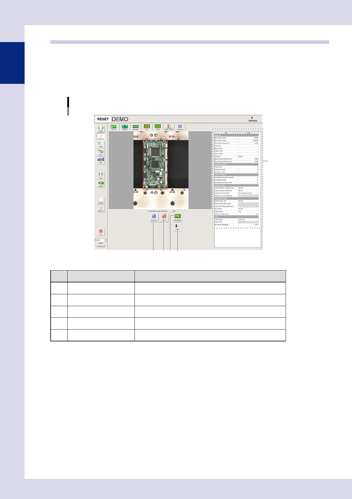
The items and buttons displayed on the "Data Edit" screen are described below.
For instructions on how to set inspection data, refer to Chapter 2, "Creating and setting data", in this manual.
1.4.1 "Board" screen
This screen allows setting the basic items needed to perform board inspection and to create entire board
images.
[Data Edit] - [Board] screen
4 52 3
1
24104-P6-00
Item/button name Function
1 Board parameter In this list, set parameter data such as board size to perform inspection.
2 Execute* Captures an entire board image.
3 Stop* Stops capturing an entire board image.
4 Data Rotate* Rotates inspection data by 90°, 180°, or 270°.
5 Width* Displays the screen for changing the conveyor width.
* This cannot be used with offline software YSi-OS (option).
1-5
1
asic operation
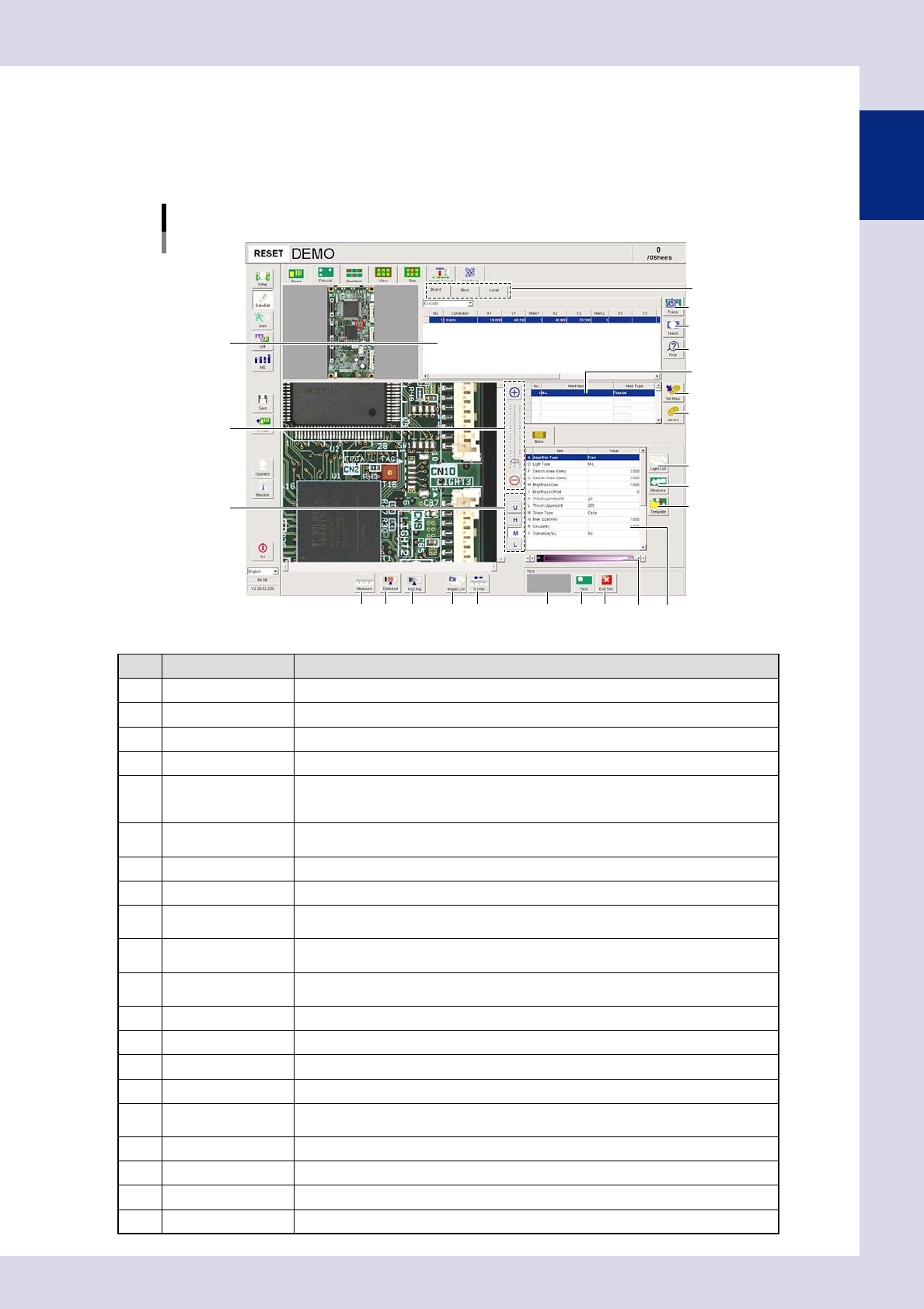
1.4.2 "Fiducial" screen
This screen allows setting fiducial marks to use the fiducial function. Based on recognition results of the
fiducial marks on the board under inspection, the fiducial function corrects local distortion or warps on the
board that may occur from errors in machining the board outline or locate pin holes, or board clamping
mechanism fluctuations.
[Data Edit] – [Fiducial] screen
1
2
3
4
7
8
9
10
12 13 14
Mark list
Mark type list
11
5
6
18 19 2016
17
Basic parameter
15
24105-P9-00
Item/button name Function
1 Board/Block/Local The unit for enabling the fiducial function can be selected from board, block, or local.
2 Trace Moves the camera to the mark XY coordinates selected in the mark list.
3 Teach The center of the recognized mark is registered as the fiducial mark position coordinates.
4 Find Searches for and replaces items registered in the block or local mark list.
5 Zoom
+ : Enlarges the fiducial mark image.
- : Reduces the fiducial mark image.
The image can also be enlarged and reduced by rotating the mouse wheel.
6 Change lighting
Changes the fiducial image lighting. Select the lighting that results in the clearest image
from U, H, M, and L.
7 Set Mark Registers the selected mark in the library.
8 Library Pastes the mark registered in the library.
9 Light List
Displays a list with the mark image illuminated under each lighting, allowing the operator
to select the most suitable lighting from the list.
10 Measure
By dragging the mouse to enclose the identified mark, parameters are measured
automatically based on the "Algorithm Type" set in the basic parameters.
11 Template
Saves template data for pattern matching. This button becomes active when pattern
matching is selected at "A. Algorithm Type" in the basic parameters.
12 Measure Measures the distance on the fiducial image.
13 Detected Displays the detected range based on the set threshold value conditions in red.
14 Insp img Displays the inspection image with the lighting selected in the lighting list.
15 Image List Selects fiducial mark images saved to the image list.
16 0.1mm
Pressing this button changes the pitch for the camera to move when the arrow buttons
on the scroll bars are pressed. (0.01mm, 0.100mm, 0.500mm, 5.000m)
17 Result display Displays the result of the fiducial mark recognition test.
18 Test Perform a fiducial mark recognition test.
19 End Test Ends a fiducial mark recognition test.
20 Threshold slide bar Displays and changes the detection threshold value.