YSI_Prog_E - 第40页
1-5 1 asic operation 1.4.2 "Fiducial" screen T his screen allows setting fiducial marks to use the fiducial function. Based on recognition results of the fiducial marks on the board under inspection, the fidu…
1-4
1
asic operation
1.4 Data Edit screen
The items and buttons displayed on the "Data Edit" screen are described below.
For instructions on how to set inspection data, refer to Chapter 2, "Creating and setting data", in this manual.
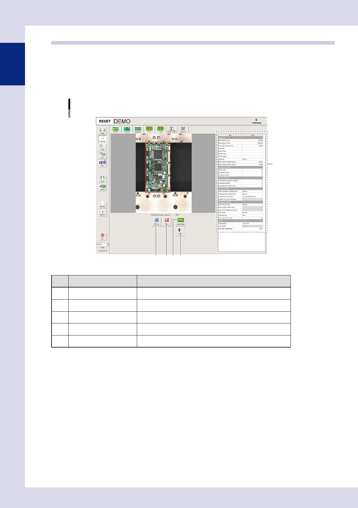
1.4.1 "Board" screen
This screen allows setting the basic items needed to perform board inspection and to create entire board
images.
[Data Edit] - [Board] screen
4 52 3
1
24104-P6-00
Item/button name Function
1 Board parameter In this list, set parameter data such as board size to perform inspection.
2 Execute* Captures an entire board image.
3 Stop* Stops capturing an entire board image.
4 Data Rotate* Rotates inspection data by 90°, 180°, or 270°.
5 Width* Displays the screen for changing the conveyor width.
* This cannot be used with offline software YSi-OS (option).
1-5
1
asic operation
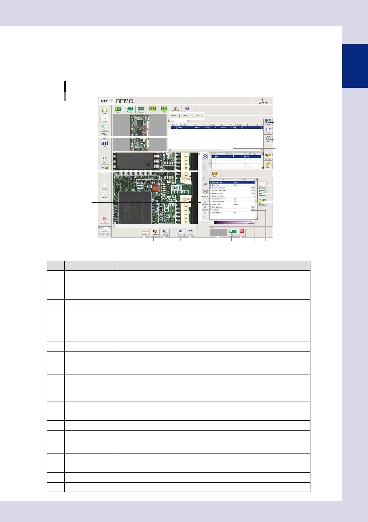
1.4.2 "Fiducial" screen
This screen allows setting fiducial marks to use the fiducial function. Based on recognition results of the
fiducial marks on the board under inspection, the fiducial function corrects local distortion or warps on the
board that may occur from errors in machining the board outline or locate pin holes, or board clamping
mechanism fluctuations.
[Data Edit] – [Fiducial] screen
1
2
3
4
7
8
9
10
12 13 14
Mark list
Mark type list
11
5
6
18 19 2016
17
Basic parameter
15
24105-P9-00
Item/button name Function
1 Board/Block/Local The unit for enabling the fiducial function can be selected from board, block, or local.
2 Trace Moves the camera to the mark XY coordinates selected in the mark list.
3 Teach The center of the recognized mark is registered as the fiducial mark position coordinates.
4 Find Searches for and replaces items registered in the block or local mark list.
5 Zoom
+ : Enlarges the fiducial mark image.
- : Reduces the fiducial mark image.
The image can also be enlarged and reduced by rotating the mouse wheel.
6 Change lighting
Changes the fiducial image lighting. Select the lighting that results in the clearest image
from U, H, M, and L.
7 Set Mark Registers the selected mark in the library.
8 Library Pastes the mark registered in the library.
9 Light List
Displays a list with the mark image illuminated under each lighting, allowing the operator
to select the most suitable lighting from the list.
10 Measure
By dragging the mouse to enclose the identified mark, parameters are measured
automatically based on the "Algorithm Type" set in the basic parameters.
11 Template
Saves template data for pattern matching. This button becomes active when pattern
matching is selected at "A. Algorithm Type" in the basic parameters.
12 Measure Measures the distance on the fiducial image.
13 Detected Displays the detected range based on the set threshold value conditions in red.
14 Insp img Displays the inspection image with the lighting selected in the lighting list.
15 Image List Selects fiducial mark images saved to the image list.
16 0.1mm
Pressing this button changes the pitch for the camera to move when the arrow buttons
on the scroll bars are pressed. (0.01mm, 0.100mm, 0.500mm, 5.000m)
17 Result display Displays the result of the fiducial mark recognition test.
18 Test Perform a fiducial mark recognition test.
19 End Test Ends a fiducial mark recognition test.
20 Threshold slide bar Displays and changes the detection threshold value.
1-6
1
asic operation
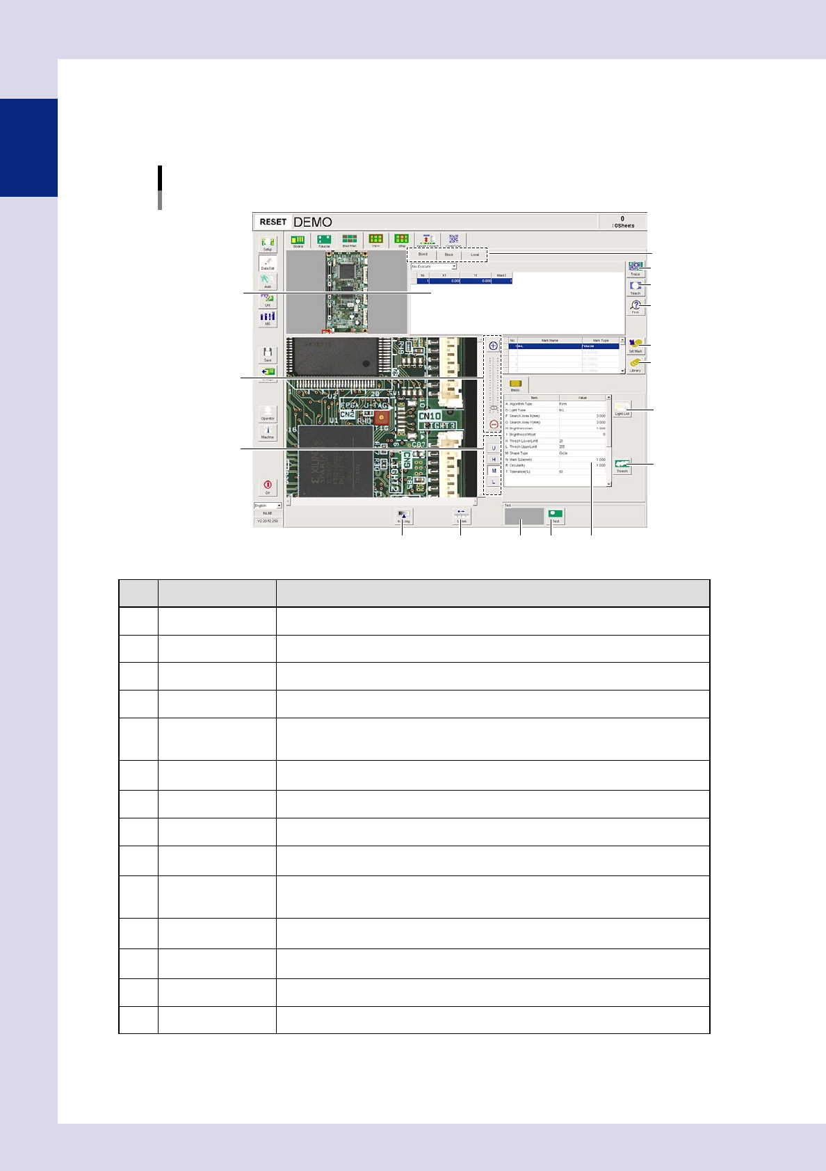
1.4.3 "Bad Mark" screen
This screen allows you to set bad marks in order to use the bad mark function. The bad mark function involves
affixing a mark (bad mark) to a set location on the board in order to ensure that inspection is not performed
when the mark is recognized by the inspection machine.
[Data Edit] - [Bad Mark] screen
1
9
11 12
10
13
14
Basic parameter
Mark list
2
3
4
7
8
5
6
24106-P6-00
Item/button name Function
1 Board/Block/Local The unit for enabling the bad mark function can be selected from board, block, or local.
2 Trace Moves the camera to the mark XY coordinates selected in the mark list.
3 Teach The center of the recognized mark is registered as the bad mark position coordinates.
4 Find Searches for and replaces items registered in the block or local mark list.
5 Zoom
+ : Enlarges the bad mark image.
- : Reduces the bad mark image.
The image can also be enlarged and reduced by rotating the mouse wheel.
6 Change lighting
Changes the bad mark image lighting. Select the lighting that results in the clearest
image from U, H, M, and L.
7 Set Mark Registers the selected mark in the library.
8 Library Pastes the mark registered in the library.
9 Light List
Displays a list with the mark image illuminated under each lighting, allowing the operator
to select the most suitable lighting from the list.
10 Thresh
Sets the threshold value used for mark recognition. By pressing this button, a "Bad mark
threshold value setting" screen appears, allowing the user to set the threshold value
when marks are detected and when not detected.
11 Insp img
Displays the view image selected in the view list. The view image can be changed even
by selecting the board image view.
12 0.1mm
Pressing this button changes the pitch for the camera to move when the arrow buttons
on the scroll bars are pressed. (0.01mm, 0.100mm, 0.500mm, 5.000m)
13 Result display Displays the result of the bad mark recognition test.
14 Test Performs the bad mark recognition test.