YSI_Prog_E - 第44页
1-9 1 asic operation Item/button name Function 13 0.1mm Pressing this button changes the pitch for the camera to move when the arrow buttons on the scroll bars are pressed. (0.01mm, 0.100mm, 0.500mm, 5.000mm) 14 Foreig…
1-8
1
asic operation
Item/button name Function
20 Step Check Displays all steps on the entire board.
21 0.1mm*
Pressing this button changes the pitch for the camera to move when the arrow buttons
on the scroll bars are pressed. (0.01mm, 0.100mm, 0.500mm, 5.000mm)
22 Existing images list
Displays whether images exist in each view for board ID images selected in the image
list.
is displayed if the image exists, and X is displayed in the image does not exist.
23 NG parts list Displays all NG parts for the entire view saved as an NG image.
* This cannot be used with offline software YSi-OS (option).
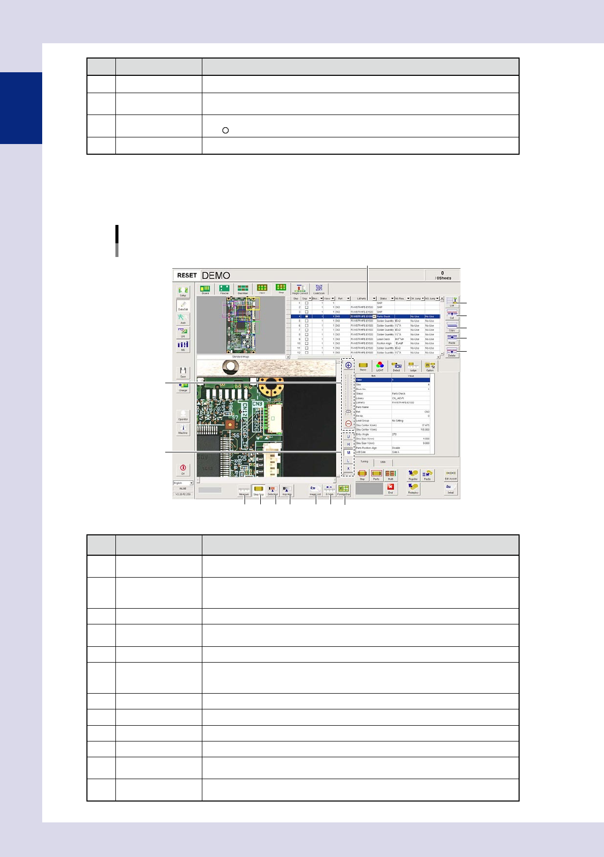
1.4.5 "Step" screen
This screen allows you to create and edit inspection steps, and to save and deploy libraries.
[Data Edit] – [Step] screen
1
2
3
4
5
8
9
11
10
12 13
6
7
14
Step data list
24108-P6-00
Item/button name Function
1 List
Displays data displayed in the step data list as all steps in the program, or as inspection
steps for the currently selected part.
2 Cut
Cuts (deletes) the selected rows and copies them to the clipboard. The data rows below
the deleted rows move up.The cut data is kept stored until different data is cut or paste
to the clipboard.
3 Copy Copies the selected rows to the clipboard.
4 Paste
Inserts and overwrites data copied to the clipboard into inspection data. Pressing this
button displays an "Add step" dialog box, allowing the add method to be selected.
5 Delete Deletes the selected data rows. The data rows below the deleted rows move up.
6 Zoom
+ : Enlarges the step image
- : Reduces the step image.
The image can also be enlarged and reduced by rotating the mouse wheel.
7 Change lighting Changes the step image lighting. Select the lighting from U, H, M, L, and X (YSi-X).
8 Measure Measures the distance on the step image.
9 Step Disp Displays or hides step frames on the screen.
10 Detected Displays the detected area in red.
11 Insp Img
Displays an image at the step frame position, by capturing it under lighting used for
inspection.
12 Image List
A list of images saved to the inspection program appears. Select the image to be
displayed from the image list.
1-9
1
asic operation
Item/button name Function
13 0.1mm
Pressing this button changes the pitch for the camera to move when the arrow buttons
on the scroll bars are pressed. (0.01mm, 0.100mm, 0.500mm, 5.000mm)
14 Foreign Disp
By specifying the number of divisions at [Edit Assist] - [?Deploy Foreign Matter Check?]
in the (Tuning) tab, created foreign matter check steps are displayed. Furthermore, steps
in the adjacent view appear in a yellow box.
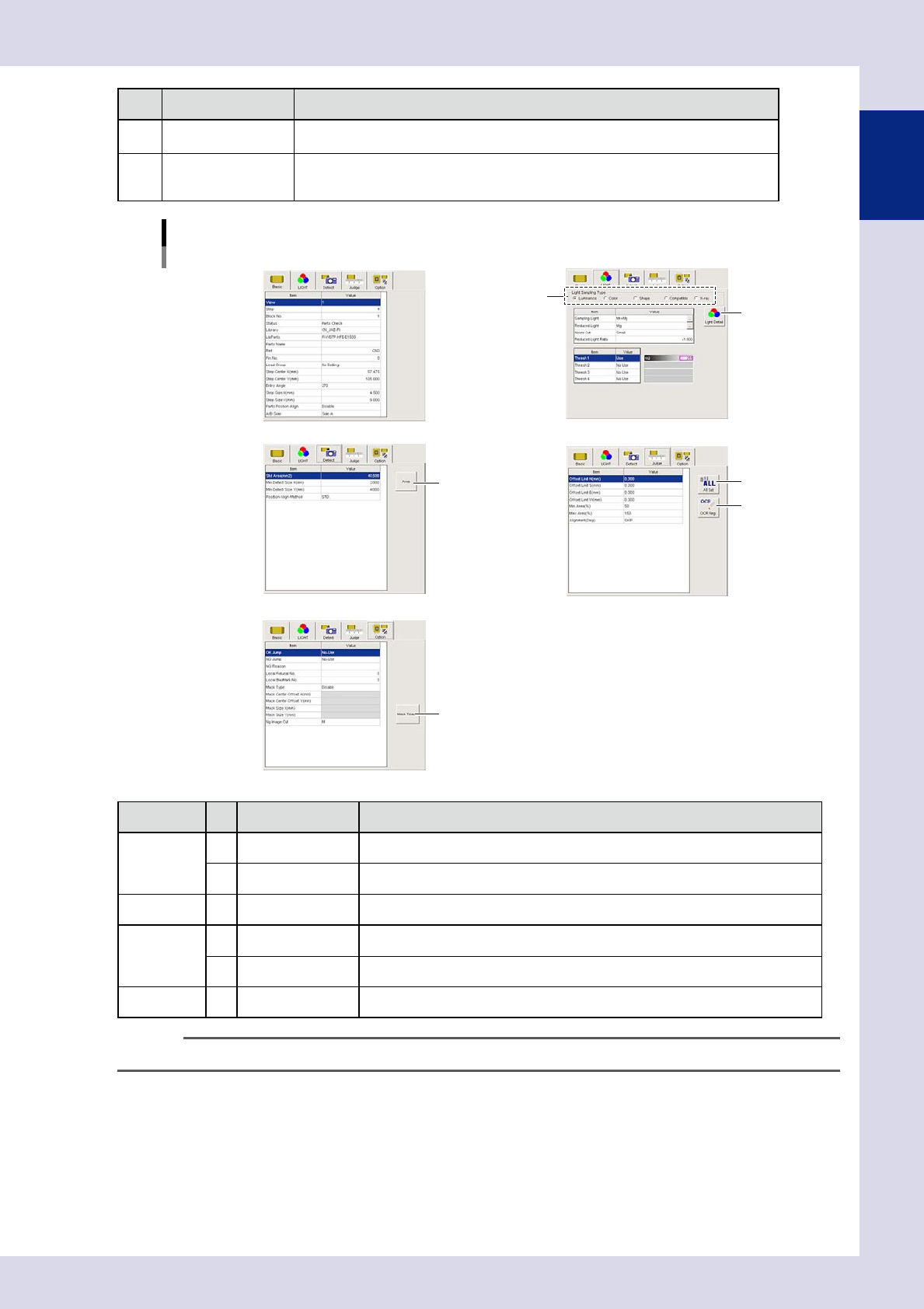
[Data Edit] – [Step] screen
Parameter screens
2
1
3
4
5
Basic Light Detail
Detect Judge
OPtion
6
24109-P9-00
Parameter Item/button name Description
LIGHT
1 Light sampling Type Selects the method used to recognize the inspection object.
2 Light Detail Specifies detailed settings used to recognize the inspection object.
Detect 3 Area By pressing this button, the area inside the step is entered in "Std Area".
Judge
4 All Set Pressing this button also sets the selected offset in other directions.
5 OCR Reg. Registers an original character font for each user as the character recognition font.
Option 6 Mask Teach Moves the mask area, and changes the size.
TIP
For details on each parameter, refer to Chapter 3, "1. Parameters", in this manual.
1-10
1
asic operation
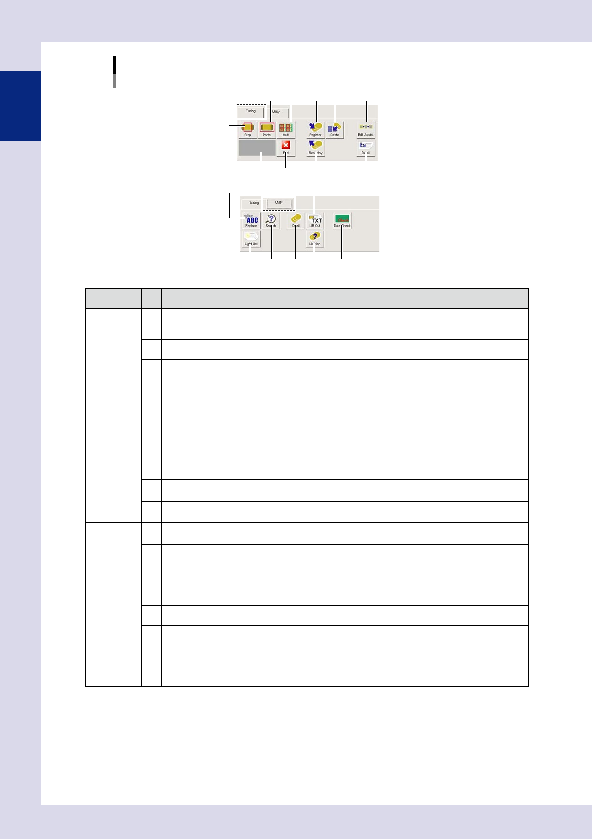
[Data Edit] – [Step] screen
[Tuning] tab、[Utility] tab
7 91 2 3 6
11
1213 14
85
15
[Tuning] tab
[Utility] tab
4 10
1716
24110-P6-00
Parameter Button name Description
Tuning
1 Step
Performs a continuous test of the selected steps, and displays the results.
Performs an inspection until the [End] button is pressed, and displays the test
results in the "Step" screen.
2 Parts Performs a test of all steps for the selected part, and displays the results.
3 Multi
Sets conditions for steps subject to inspection, and performs a test. (See Chapter
3, "2.4.1 Multi-test", in this manual.)
4 Result display Displays the test results.
5 End Ends the test.
6 Register Registers the steps for the selected part in the library.
7 Paste Pastes the selected library to parts on the step image.
8 Redeploy Deploys libraries to inspection data under the set conditions.
9 Edit Assist
Copies steps, adds pin Nos., deploys arrangement and pin information, and
deploys foreign matter checks. (See Chapter 3, "3 Edit assist", in this manual.)
10 Detail
All results can be checked when the test is complete. (See Chapter 3, "2.4.2
Measurement results", in this manual.)
Utility
11 Replace
Sets conditions, and replaces parameters for the relevant step at one time. (See
Chapter 3, "4.1 Replace", in this manual.)
12 Search
Set the type and character string for the inspection object at the "Search" screen,
and press the [Next Search] button to jump to the relevant step. (See Chapter 3,
"4.2 Search", in this manual.)
13 Light List
Displays a list of recognized images with the YAMAHA standard lighting settings.
Furthermore, new lighting settings can be registered, and lighting settings can be
set to steps.
14 Detail Displays details of the selected library.
15 Lib Out Outputs the library in text format.
16 Lib Non
Displays the "Library unset parts" screen, and displays steps to which no library
has been pasted in a list.
17 Data Check Checks for inconsistencies in inspection data.