YSI_Prog_E - 第48页
1-13 1 asic operation 1.5 Auto inspection screen Press the [Auto] button to perform automatic board inspection. T his section describes the screen items and buttons that appear when the [Auto] button is pressed. 1.5.1 …
1-12
1
asic operation
1.4.7 "Code Scan" screen
The code scan function is used to read QR Codes and so on affixed to boards to identify boards IDs. Board IDs
are used when outputting SPC data, and when outputting results to the Repair Station (option).
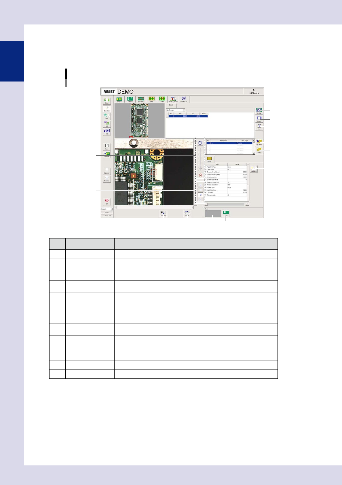
This screen allows you to set and edit code scan conditions.
[Data Edit] – [Code Scan] screen
2
3
6
5
1
4
7
8
12109
11
24112-P6-00
Item/button name Function
1 Trace Moves the camera to the mark list XY coordinates.
2 Teach
The center of the recognized mark is registered as the fiducial position
coordinates.
3 Find Searches for and replaces items registered in the mark list.
4 Zoom
+ : Enlarges the code scan image.
- : Reduces the code scan image.
5 Change lighting
Changes the code scan image lighting. Select the lighting that results in the
clearest mark image from U, H, M, and L.
6 Set Mark Registers the selected mark in the library.
7 Library Sets the mark information registered in the library.
8 Light List
Displays a list with the mark image illuminated under each lighting, allowing the
operator to select the most suitable lighting from the list.
9 Insp Img
Displays the code scan image captured with the lighting used to perform
inspection in the code scan position.
10 0.1mm
Pressing this button changes the pitch for the camera to move when the arrow
buttons on the scroll bars are pressed. (0.01mm, 0.100mm, 0.500mm, 5.000m)
11 Result display Displays the code scan test results.
12 Test Performs the code scan test.
1-13
1
asic operation
1.5 Auto inspection screen
Press the [Auto] button to perform automatic board inspection.
This section describes the screen items and buttons that appear when the [Auto] button is pressed.
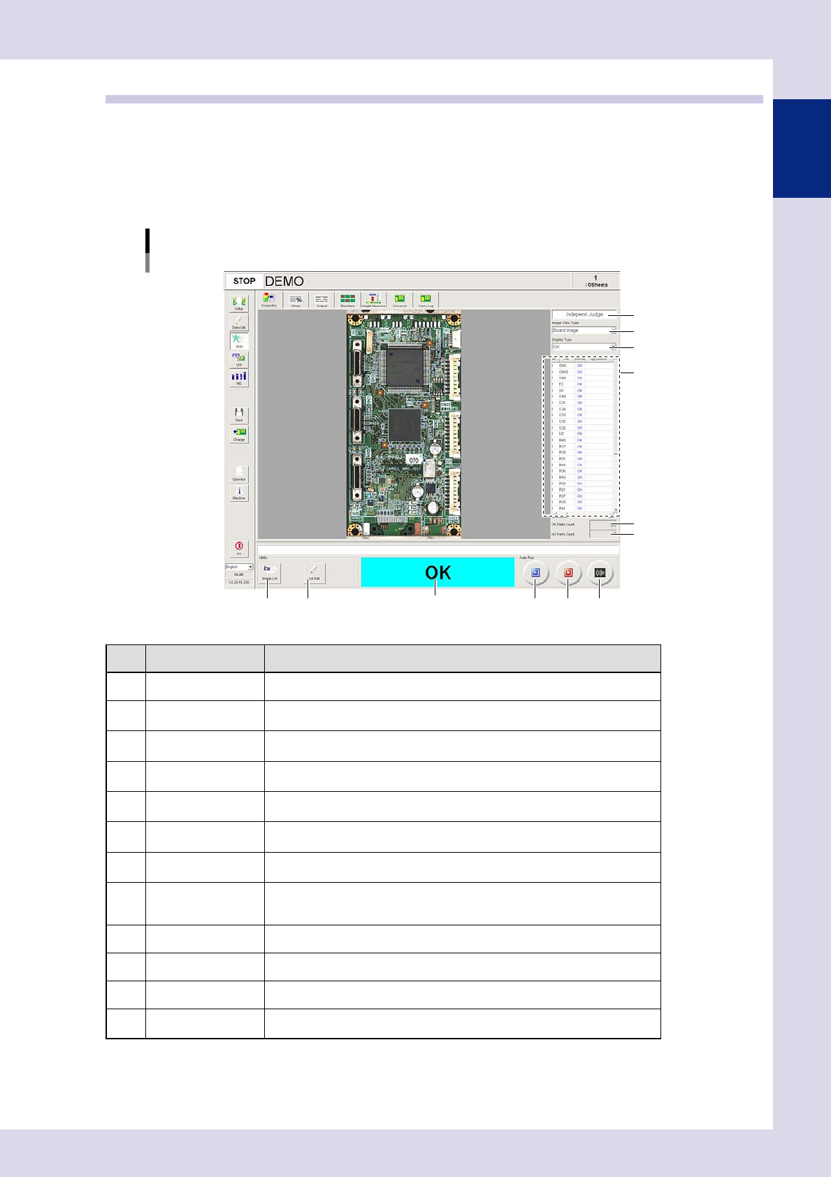
1.5.1 "Inspection" screen
This screen allows you to perform and stop automatic inspection. Inspection judgment information is also
displayed.
[Auto] – [Inspection] screen
2
4
5
1
912 10
6
3
7 8
11
24113-P6-00
Item/button name Description
1 Judgment Mode Displays optional software used to send inspection results to the Repair Station.
2 Image View Type
Selects and displays the image display. Select the display type from the
drop-down list.
3 Display Type
Selects and displays the inspection results displayed in the results details list.
Select the display type from the drop-down list.
4 Rsult detail
Displays inspection steps for the inspection results specified in "Display Type".
(No steps are displayed if the no Ref. Nos. have been set for the steps.)
5 OK Parts Count
The number of parts for which an OK inspection result was obtained is
displayed.
6 NG Parts Count
The number of parts for which an NG inspection result was obtained is
displayed.
7 Image List
Inspects images saved to the inspection program. Pressing this button displays
an "Image list" screen. Select an image and then press the [Select] button.
8 Lot Edit
This button appears when "Use" is set in "Server Settings"
→
"Lot Unit
Management" in the machine settings. Pressing this button displays a "Lot input"
screen, allowing the lot No. and production quantity to be edited.
9 Run Starts the inspection.
10 Stop Stops the inspection.
11 Buzzer off Stops the buzzer.
12
Inspection result
display field
Displays the board inspection result.
1-14
1
asic operation
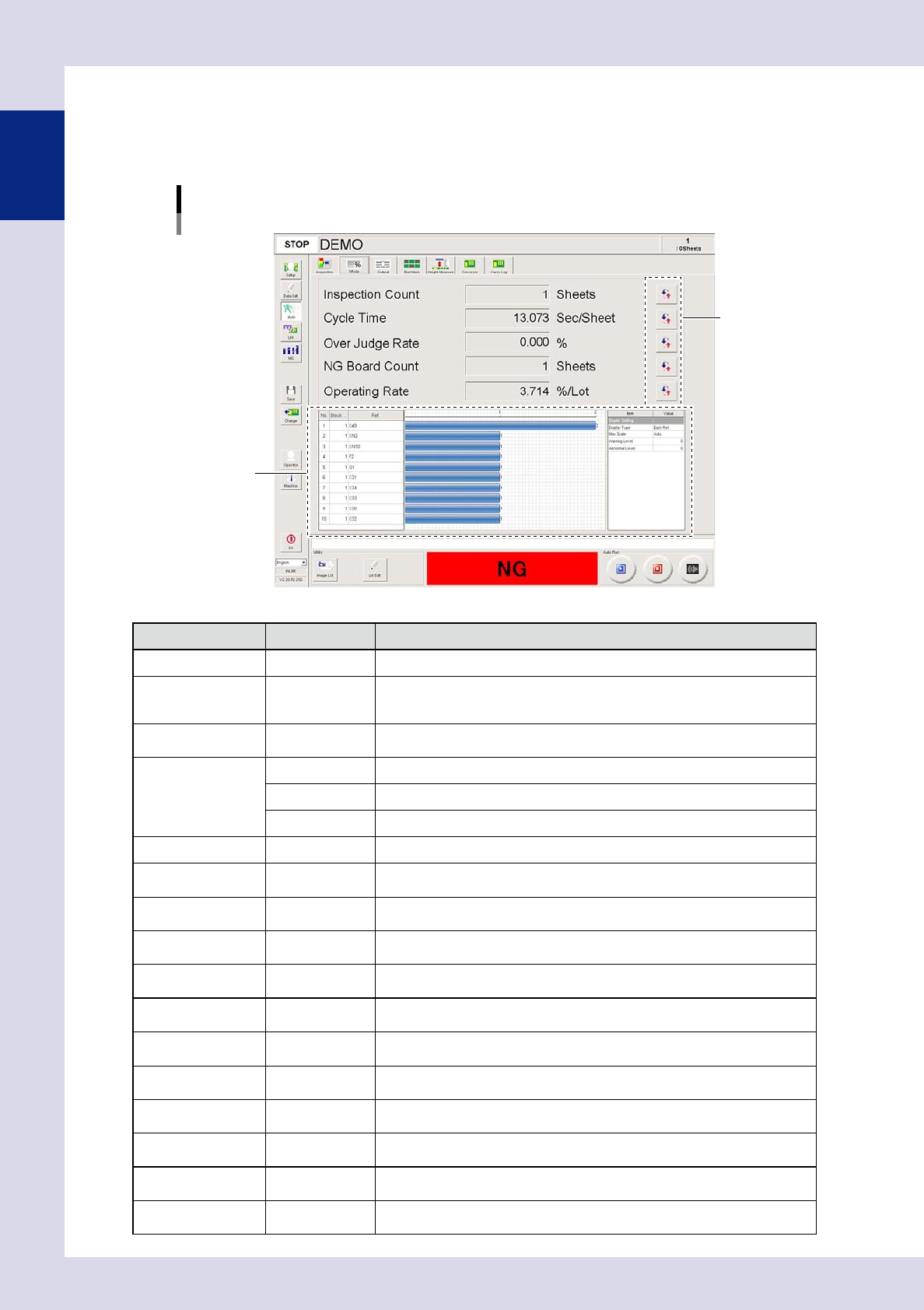
1.5.2 "Whole" screen
This screen displays the inspection state in real-time, such as the number of boards that have been inspected.
When the inspection program is changed, information related to that inspection program will be cleared.
The displayed items can be changed by pressing the [Display Change] button on the right side of each item.
[Auto] – [Whole] screen
[Display Change] button
NG information
24114-P6-00
Item/button name
Units Description
Display Change Changes the displayed item.
Inspection Count Sheet
Shows the number of boards inspected after the current inspection program is
selected.
Boards for which inspection is stopped before it is completed will not be counted.
Total Count Sheet
Shows the total number of boards inspected after the inspection machine
application software is started.
Cycle Time
Sec/Sheet This is the average inspection time per board.
Sec/Step This is the average inspection time per step.
Sec/Parts This is the average inspection time per part.
Over Judge Rate % OK CONT count / number of inspected steps × 100 (%)
First-Pass Rate %
This is the number of OK boards divided by the number of inspected boards and
then multiplied by 100 (%).
NG Rate %
Number of defective boards / number of inspected boards × 100 (%). This is
counted after the current inspection program is selected
Parts NG Rate %
NG count for each Ref / total Ref count (number of parts) × 100 (%). This is
counted after the current inspection program is selected.
Total NG Rate %
Total number of defective steps / total number of inspected steps × 100 (%). This
is counted after the inspection machine application software is started.
NG Board Count Sheet
Displays the number of NG boards after changing to the inspection program
currently being used to perform inspection.
Total NG Board Count Sheet
Displays the total number of NG boards since the inspection machine application
was started.
First-Pass Count Sheet
Displays the number of OK boards after changing to the inspection program
currently being used to perform inspection.
NG Count Step
Displays the number of NG steps after changing to the inspection program
currently being used to perform inspection.
Total NG Count Step
Displays the total number of NG steps since the inspection machine application
was started.
Operating Rate %/lot
Average inspection time × (number of inspected boards) / machine's cumulative
inspection time
Working Rate %/lot
Average inspection time × (number of inspected boards) / (machine's cumulative
inspection time – board wait time – board unloading wait time)