YSI_Prog_E - 第74页
2-3 2 Inspection data creation and tuning n Detection conditions: lighting selection Select the lighting best able to judge the inspection object clearly , and specify settings for performing inspection with only the ins…
2-2
2
Inspection data creation and tuning
1.2 Inspection method
This section describes the optical inspection method and X-ray inspection method used by YSi Series inspection
machines.
The models and corresponding inspection methods are shown in the following table.
Model Inspection method
YSi-S Optical inspection + laser unit height measurement *
YSi-12 Optical inspection + laser unit height measurement *
YSi-X Optical inspection + X-ray inspection + laser unit height measurement *
* Laser unit height measurement is optional.
n
NOTE
The inspection head and board movement when performing inspection differ depending on the model.
• YSi-S
The inspection head moves in the left and right directions, and the board moves in the forward and back directions.
• YSi-12
The inspection head moves back, forth, left and right above the board.
• YSi-X
The board moves below the inspection head.
1.2.1 Optical inspection
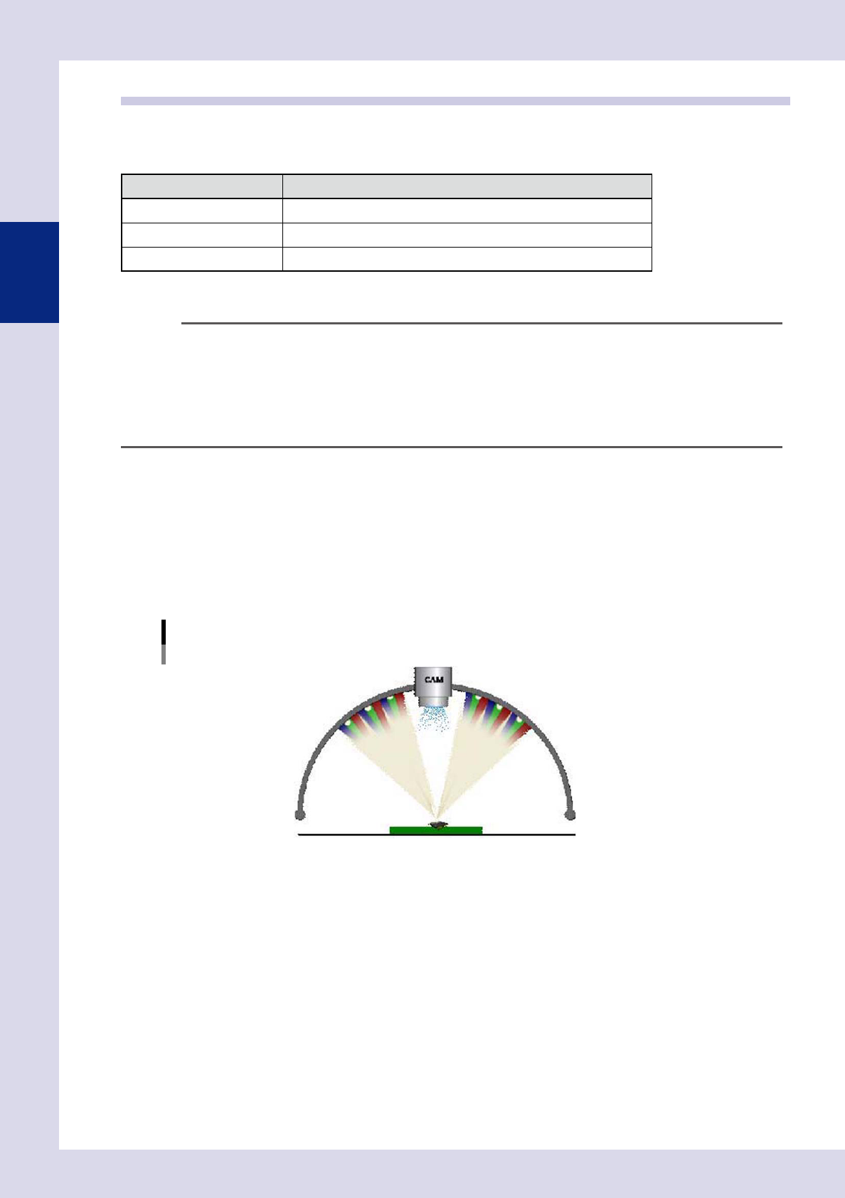
YSi Series inspection machines employ a 3-stage dome lighting method, and by arranging a digital color
camera for inspection in the center of the dome lighting, images are captured without silhouettes. The upper
stage uses white light LEDs (R, G, B) and infrared rays, the middle stage uses white light LEDs (R, G, B), and the
lower stage uses white light LEDs (R, G, B). The lighting best able to judge the inspection object clearly can be
selected from ten different types. By selecting the optimum lighting for the inspection object and setting
conditions for showing the inspection object in red, an OK or NG result is judged by comparing the surface
area and position shown in red with the judgment conditions.
3-stage dome lighting
U: Upper lighting (IR), H: Upper lighting
M: Middle lighting
L: Lower lighting
23203-P6-00
2-3
2
Inspection data creation and tuning
n
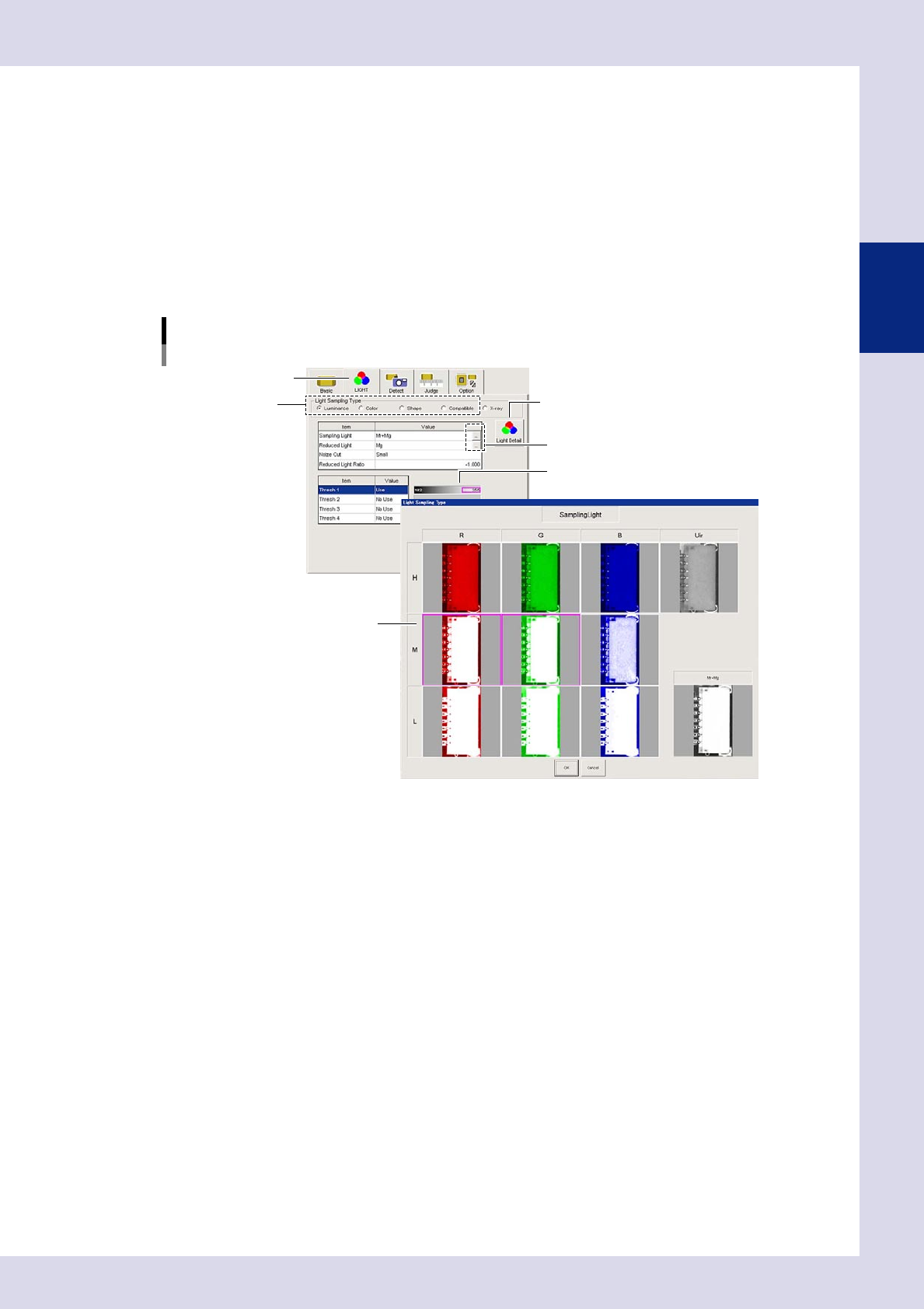
Detection conditions: lighting selection
Select the lighting best able to judge the inspection object clearly, and specify settings for performing inspection with
only the inspection object shown in red. For each step, open the "LIGHT" tab at the [Inspection Program] - "Step" screen,
and select the lighting detection type from "Luminance", "Color", or "Shape".
This section describes the lighting selection if "Luminance" is selected.
1. Click the image list buttons to the right of the sampling light and reduced light values fields to display a list of sampling
light images.
2. Select a lighting that offers good contrast between the area being inspected and the surrounding area (lighting with
which difference in brightness is clearly visible) from the list of sampling light images, and then press the [OK] button.
3. Adjust "Thresh 1” with the threshold slide bar to set the threshold value that shows the inspection area in red.
4. Set the conditions for the inspection object from the area shown in red in the detection conditions parameters.
Image list
Sampling light example
[Light Detail] button
"LIGHT" tab
Sampling light type
Image list buttons
Threshold slide bar
Sampling light type image list
24201-P6-00
n
Judgment conditions
Set the reference for judging OK or NG for the inspection object detected in red with the detection conditions. The
parameters to be set differ depending on the inspection status. For details on the inspection status, see Chapter 4,
"Inspection status", in this manual.
2-4
2
Inspection data creation and tuning
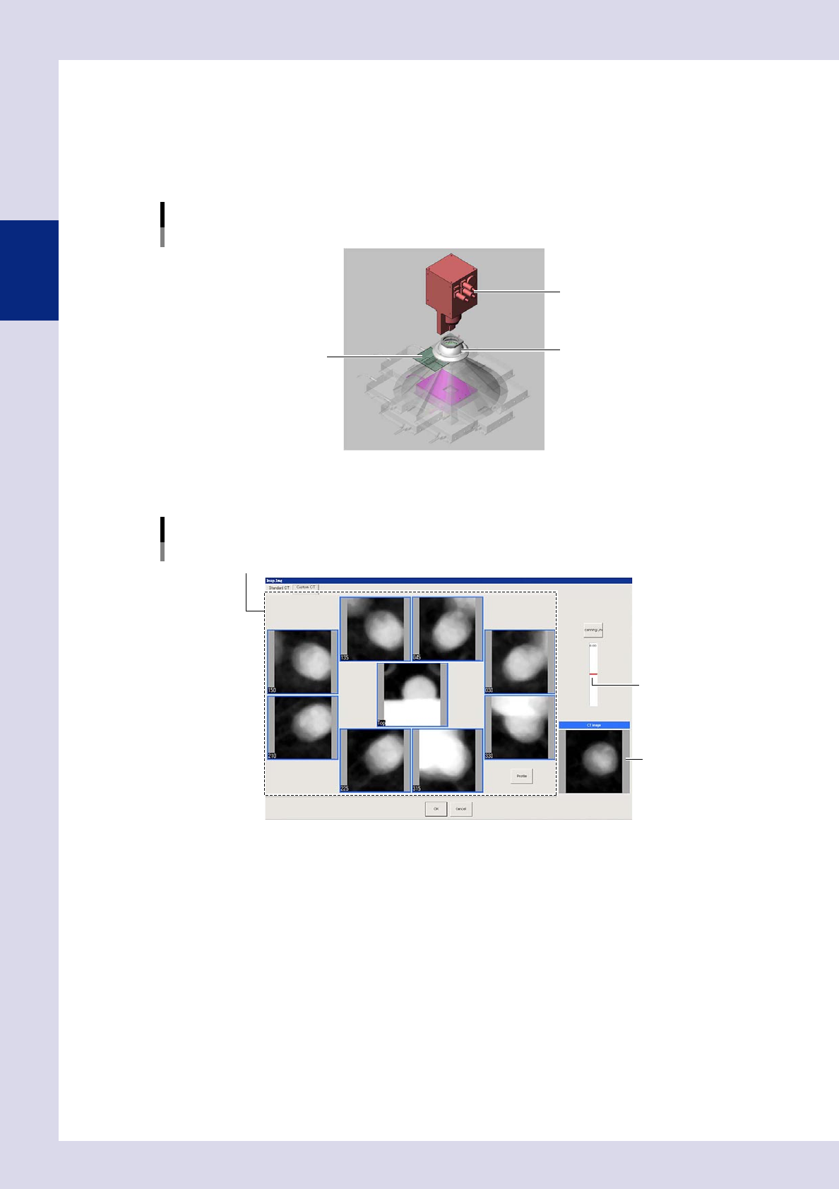
1.2.2 X-ray inspection
X-ray inspection is used to inspect solder joints on lower surface electrode parts and the back fillet of leaded
parts, and solder on parts mounted on the lower surface. Tomographic imaging is possible with digital
laminography, and so height inspection can be performed with height set. Inspection is performed by
compensating for board warp, and therefore laser unit height measurement is used. The resolution can be
changed to 12, 19, 27, and 54 μm for each field-of-view based on the size of the inspection object.
Inspection image selection image
X-ray source
Dome lighting
Board
23204-P6-00
X-ray inspection involves setting the inspection height and creating X-ray horizontal tomographic images based
on an aerial X-ray image and X-ray images from up to eight different directions.
X-ray inspection image
Inspection image
Set the insection height.
Aerial (center) image, images from eight directions
24202-P6-00