YSI_Prog_E - 第83页
2-12 2 Creating inspection pr ograms 2.3 Creating full board images If creating a new inspection program, it is necessary to create and sa ve a full board image. Sa ved full board images are used only as images for displ…
2-11
2
Creating inspection programs
3
Select the file to be converted and press the [Convert] button.
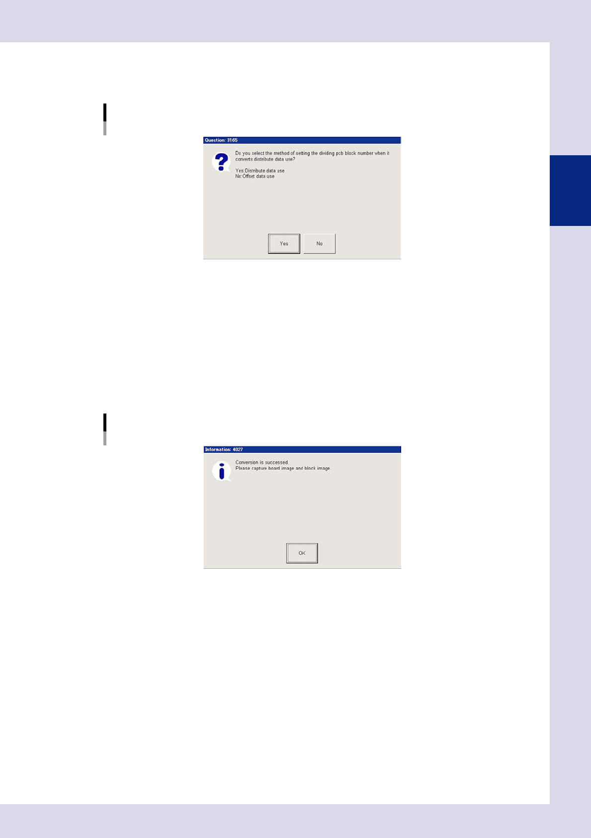
1. A multi-board panel block No. setting confirmation dialog box appears. Check the contents and
press the relevant button to perform data conversion.
Multi-board panel block No. setting confirmation dialog box
24206-P6-00
Yes
Uses reference data.
Select to convert data for blocks for which block deployment is complete.
No
Uses offset information.
Select to convert data for boards with only one block, or for boards for which no blocks have been
deployed.
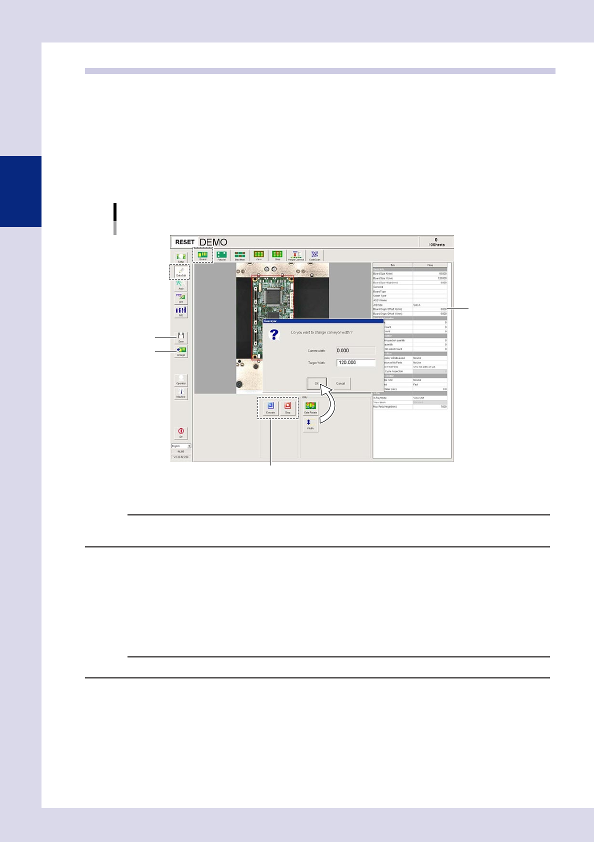
2. A conversion complete dialog box appears when conversion is complete. Press the [OK] button to
return to the "Setup" screen.
Conversion complete dialog box
24207-P6-00
3. The name of the converted program appears in the status area, and the converted inspection
program is added to the program list.
2-12
2
Creating inspection programs
2.3 Creating full board images
If creating a new inspection program, it is necessary to create and save a full board image. Saved full board
images are used only as images for displaying the entire board, and are not used for inspection. This section
describes how to create full board images for inspection programs converted from YAMAHA mounter mount
data.
1
Press the [Data Edit] button and open the "Board" tab.
2
Press the [Width] button to change the conveyor width.
A conveyor width change dialog box appears. Ensure that the conveyor width after changing is the
same as "Board Size Y (mm)", and then press the [OK] button.
Conveyor width change
Step3
Step4
Step5
Step6
24208-P6-00
TIP
If using push up pins (option), set in positions where they will not interfere with the conveyor rails or other parts when
the push up plate is raised.
3
Press the [Change] button.
A confirmation dialog box appears. Place a board at the entrance and press [Yes]. The board is then
loaded and secured at the inspection position.
4
Press the [Execute] button.
The camera head moves at the specified pitch, an image of the board is captured, and a full board
image is created. Press the [Stop] button to cancel image capture.
n
NOTE
If the board size has not been entered in "Board Size X, Y (mm)", enter the correct board size.
5
Press the [Save] button.
Press the [Yes] button at the save confirmation dialog box that appears.
2-13
2
Creating inspection programs
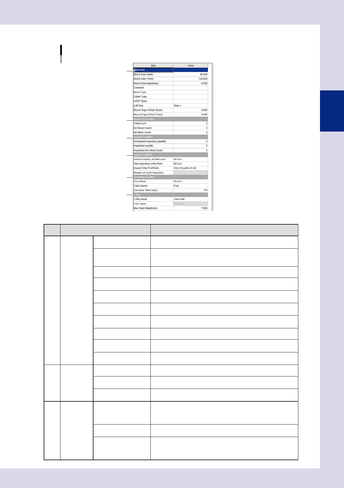
6
Enter board parameters as needed
Board parameter
1
2
3
4
5
6
24209-P6-00
Item Description
1 Basic Info.
Board Size X (mm)
Enter the board X direction size.
This is the board flow direction size.
Board Size Y (mm)
Enter the board Y direction size.
This is the conveyor width direction size when the board is placed on
the conveyor.
Board Size Height (mm) Enter the board thickness. This may be left blank.
Comment
Enter a comment on the board in this field. Up to 28 alphanumeric
characters can be entered. You can leave this field blank.
Board Type
Enter a comment on the board type in this field. Up to 28 alphanumeric
characters can be entered. You can leave this field blank.
Solder Type
Enter a comment on the solder in this field. Up to 28 alphanumeric
characters can be entered. You can leave this field blank.
Assy Name
Enter the ASSY name to be set for the board ID.
Enter eight single-byte alphanumeric characters. This may be left blank.
A/B Side Select the panel surface from side A and side B.
Board Origin Offset X
(mm)
Enter the board origin X direction offset amount.
Board Origin Offset Y
(mm)
Enter the board origin Y direction offset amount.
2 Product
Information
Total Count The total inspection board quantity is displayed after being initialized.
NG Board Count
The number of NG boards is displayed after selecting the inspection
program.
NG Block Count
The number of NG blocks is displayed after selecting the inspection
program.
3 Product
Condition
Scheduled Inspection
guantity
Enter the scheduled inspection quantity.
If "0" is entered, inspection is continued as long as boards are loaded.
If a value other than "0" is entered, operation stops when inspection of
the entered board quantity is complete. The next board is not loaded.
Inspected guantity
The inspection quantity is displayed after selecting the inspection
program. The default value is "0".
Inspection NG Abort
Count
When the NG inspection quantity for each board reaches the value
entered here, "Incomplete" is displayed for the inspection result, and
auto inspection is stopped. The board moves to the stop setting position
specified in "Conveyor setting" in the machine settings.