00195044-12_UM_VisionTeachStation_DE EN.pdf - 第116页
4 Setting up the vision teach station Vision Teach Station User Manual 4.2 Connections and LED displays on the base module 05/2014 Edition 116 4.2 Connections and LED displays on the base module 4 Fig. 4.2 - 1 Connectors…

Vision Teach Station User Manual 4 Setting up the vision teach station
05/2014 Edition 4.1 Requirements for the installation site
115
4 Setting up the vision teach station
4.1 Requirements for the installation site
4.1.1 Ambient conditions
The vision teach station is approved for use in production and in the office. The area around it must
be clean and free from dust.
4.1.2 Electrical connection
4
Tab. 4.1 - 1 Electrical ratings
4
4.1.3 Set-up location for the base module
CAUTION 4
The base module weighs around 30 kg.
You should therefore place the base module on a stable surface that is clean and level.
Two people will be needed to move the base module because of the weight.
Component Supply voltage
Base module 100 VAC to 240 VAC, 50/60 Hz
PC with wide-range power supply
PC with 115 VAC/230 VAC changeover switch
100 VAC to 240 VAC, 50/60 Hz
100 VAC to 127 VAC, 200 VAC to 240 VAC
TFT monitor with wide-range power supply 100 VAC to 240 VAC, 50/60 Hz
4 Setting up the vision teach station Vision Teach Station User Manual
4.2 Connections and LED displays on the base module 05/2014 Edition
116
4.2 Connections and LED displays on the base module
4
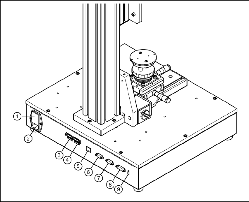
Fig. 4.2 - 1 Connectors and LED displays on the base module
(1) Power switch and fuse holder for the 2.5 A fuse
(2) Power socket (110 VAC to 240 VAC)
(3) Connection for cable, head camera 1 (03040353-W1: 26-pin, 03040353-W2: 12-pin)
(4) Connection for cable, head camera 2 (03040353-W1: 26-pin, 03040353-W2: 12-pin)
(5) Connection for camera bus cable to the PC (03040359-xx) (only if head camera is installed)
(6) Connection for CAN bus cable to the PC (03040362-xx)
(7) Connection for CAN bus cable to the stationary camera (03040355-W2)
(8) Connection for the power supply cable for the stationary camera (03040355-W1)
(9) LED displays for supply voltages, from top to bottom:
+ 24 VDC- (red)
+ 15 VDC- (yellow)
+ 42 VDC- (green)
Vision Teach Station User Manual 4 Setting up the vision teach station
05/2014 Edition 4.3 Camera and CAN bus connections on the PC
117
4.3 Camera and CAN bus connections on the PC
4
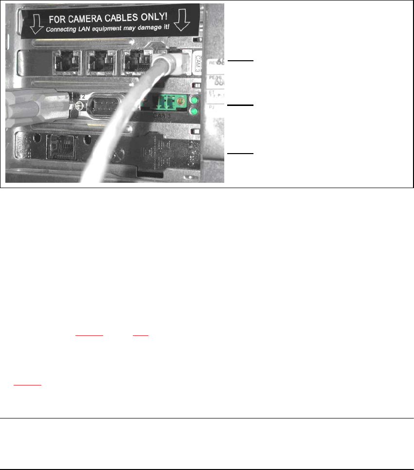
Fig. 4.3 - 2 Connectors and LED displays on the base module
(1) Camera bus interface with 4 connections
(2) CAN bus interface with 2 connectors
(3) SIPLACE LAN interface
4.4 Connecting the CAN bus between base module and PC
Connect the 3 m CAN bus cable (item no. 003040362-xx) to the connector on the base module
(item 6 in Fig. 4.2 - 1, page 116).
Tighten the two screws to secure the connector.
Plug the CAN bus cable into one of the two sockets on the CAN bus interface (item 2 in Fig.
4.3 - 2).
Tighten the two screws to secure the connector.
NOTE 4
The procedure for connecting the camera bus cable is described in the sections for the different
cameras.
(1)
4
(2)
4
(3)