00195346-0302_SM_WPC4_EN.pdf - 第23页
Replacing Spare Parts Replacing the Feed Axis Drive M otor [03047364-xx] Drive Unit – Feed Axis Service Manual SIPLACE WPC4 23 3.4.2 Replacing the Feed Ax is Drive Motor [03047364-xx] X Loosen the two mo tor support fast…
Replacing Spare Parts
Drive Unit – Feed Axis Preparations
22 Service Manual SIPLACE WPC4
3.4 Drive Unit – Feed Axis
3.4.1 Preparations
Tools required
Water pump pliers
Standard tool with set of Allen wrenches
Setting gauge, large, for collision light barrier [03051814-01]
Setting gauge, small [03052363-02]
Belt tension measuring device [00326015-01] with instruction guide
Required preparations
X Move the tower into the refill position.
X Remove all waffle pack tray carriers (WPTCs) from the tower.
X Move the tower downwards.
SITEST => menu
Functions
=> button
Transport position
.
X Switch the WPC4 off at the main switch.
X Unplug from the power supply and secure the WPC4 to prevent unauthorized reactivation.
X Undock the WPC4 from the SIPLACE machine and move it to a suitable position for service work.
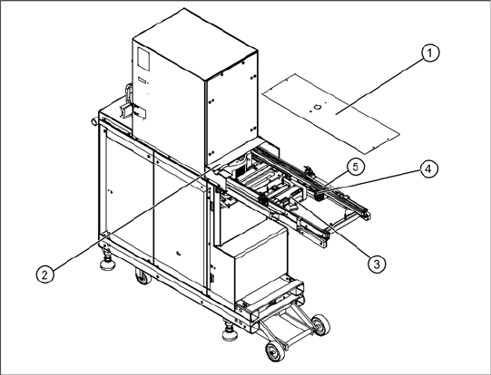
Overview
1. Feed axis cover
2. Bridge cover (safety cover on tower)
3. Feed axis drive motor
4. Drive toothed belt
5. Feed axis toothed belt
Replacing Spare Parts
Replacing the Feed Axis Drive Motor [03047364-xx] Drive Unit – Feed Axis
Service Manual SIPLACE WPC4
23
3.4.2 Replacing the Feed Axis Drive Motor [03047364-xx]
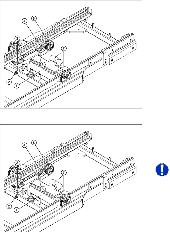
X Loosen the two motor support fastening screws (3) sealed with locking varnish.
X Loosen (do not remove) the tensioning screw (2) on the tensioning device. This relaxes the drive
toothed belt.
X Loosen and remove the 2 fastening screws (3) and then remove the drive motor with motor support.
Make sure that the drive toothed belt (4) is not buckled or damaged.
X Mark the installation position of the drive motor on the motor support.
X Loosen the 4 drive motor fastening screws (4) on the motor support.
X Fit the new drive motor with the 4 fastening screws (6) to the motor support. Observe the original
installation position.
Spare part
Feed axis motor, compl. [03047364-01]
Overview
1. Feed axis motor, compl.
2. Tensioning screw
3. 2 x motor support fastening screws
4. Toothed belt for the drive
5. Deflection pulley
6. 4 x drive motor fastening screws
7. Electrical connections
Removal/Installation
X Unscrew the electrical connections (7).
X1 orange cable = power cable
X2 green cable = control cable
NOTE: Screw joints difficult to
loosen
Each screw joint has an O-ring seal.
This can make opening the screw joint
difficult.
X Use a pair of water pump pliers to
help you unscrew the connection.
X Make sure that the O-rings do not fall
out of the screw joint and that they
are not damaged.
X When refitting, grease the thread
and the O-rings with a little Vaseline.
Replacing Spare Parts
Drive Unit – Feed Axis Replacing the Feed Axis Drive Motor [03047364-xx]
24 Service Manual SIPLACE WPC4
X Set the final belt tension. To do this, tension the drive toothed belt at the tensioning device, with the
help of the tensioning screw (2). This moves the motor support accordingly in the slots.
Setting value: Set the belt tension to 260 Hz. +/- 10 Hz.
X Tighten the 2 fastening screws (3) on the motor support, check the belt tension and adjust where
necessary.
X Seal the 2 fastening screws (3) with locking varnish.
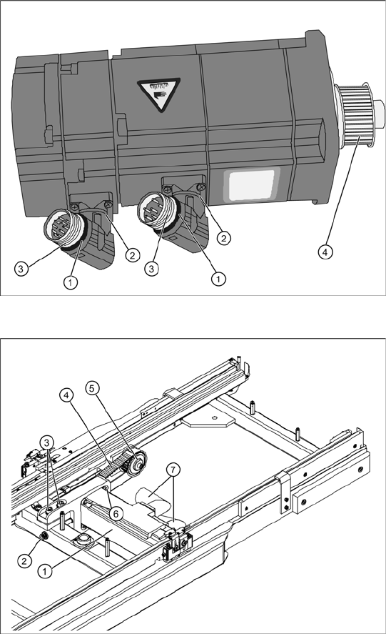
Overview of motor
1. O-ring
2. Rotary connection
3. Thread
4. Motor pinion
X The motor connections can be rotated by
hand. Rotate the connections to the position
the motor was installed in before.
X Grease the thread (3) and the O-rings (1) with
a little Vaseline.
X Move the motor and motor support into the
installation position and run the drive toothed
belt (4) around the motor pinion and around
the deflection pulley (5).
X Reconnect the electrical connections with the
motor. When fitting, note that there is an anti-
twist lock (notch) present. Tighten the
connection appropriately.
X Tension (pretension) the drive toothed belt at
the slot provided, with the help of the motor
support. Make sure that the drive toothed belt
(4) is not buckled or damaged.
X Loosely fix the motor support and drive motor
into the installation position, with the 2
fastening screws (3).