00195346-0302_SM_WPC4_EN.pdf - 第30页
Replacing Spare Parts Control Unit and Power Supply Unit Setting the Feed Axis Belt T ension 30 Ser vice Manual SIPLACE WPC4 3.5 Control Unit and Power Supply Unit Front side X Remove the 4 screws (1) fastening the side …
Replacing Spare Parts
Setting the Feed Axis Belt Tension Drive Unit – Feed Axis
Service Manual SIPLACE WPC4
29
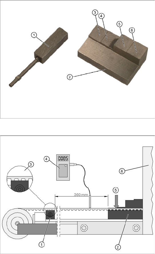
3.4.5 Setting the Feed Axis Belt Tension
Tools/equipment
Setting gauge, small [03052363-xx] (1)
Setting gauge, large, collision light barriers
[03051814-xx] (2)
Belt tension measuring device [00326015-xx]
with instruction guide
Measurement setup - measuring the feed
axis belt tension
Please note, that the bridge cover has been
removed in this diagram.
X Push the two setting gauges (1) + (2) under
the toothed belt, at a distance of 360 mm.
The large setting gauge (2) is against the
tower cover (6).
The teeth of the toothed belt (3) must lie on the
setting gauge.
X Press the large setting scale downwards with
a suitable object or with your finger, so that the
toothed belt lies on the gauge (5).
X Adjust the belt tension. To do this, gently pull
the toothed belt or tap it with an Allen wrench,
so that it starts swinging and then measure the
value with the belt tension measuring device.
The belt tension must be 85 Hz. +/-5 Hz..
Replacing Spare Parts
Control Unit and Power Supply Unit Setting the Feed Axis Belt Tension
30 Service Manual SIPLACE WPC4
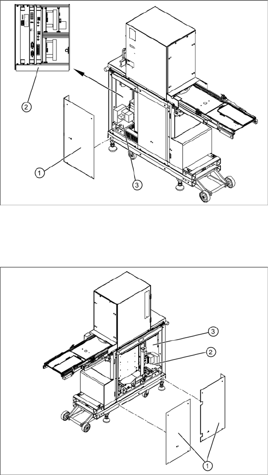
3.5 Control Unit and Power Supply Unit
Front side
X Remove the 4 screws (1) fastening the side
covers. Underneath, you will see the front end
of the control unit (2) and the front end of the
power supply unit (3).
The front end of the control unit contains the
Servo and axis controller boards
Ballast circuit
Power supply board
Controller board
The front end or installation plate of the power
supply unit contains the
Protective contactor combination SSK – K1
Contactors K2/K3
Primary and secondary transformer fuses
Back
X Remove the 8 screws (1) fastening the two
side covers. Underneath, you will see the back
of the control unit (3) and the back of the power
supply unit (2).
The back of the control unit contains the terminal
strips and the plug-and-socket connections,
the limit switches, sensors and light barriers
The drive motors (lifting and feed axis)
The fan connection etc.
The back part or installation plate of the power
supply contains the
Inrush current limitation board A1 with K4
Line filter for 3-phase system
Rectifier bridge
Transformer
Replacing Spare Parts
Control Unit Control Unit and Power Supply Unit
Service Manual SIPLACE WPC4
31
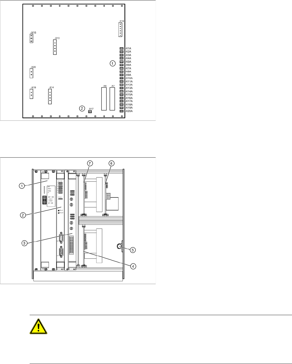
3.5.1 Control Unit
3.5.1.1 Instructions for Working with Control Units
View of back - details
1. Connections for limit switches, sensors and
light barriers
2. Fan connection
X For connection details and complete circuit
diagrams, please refer to the following
documentation:
SIPLACE D1 detailed circuit diagrams
[00194841-xx] German
SIPLACE D1 detailed circuit diagrams
[00194841-xx] English
Overview
1. Supply board
2. Controller board
3. Axis controller board KSP A364 analog
4. Servo amplifier for lifting axis (10A)
5. Braking resistor for lifting axis
6. Ballast circuit
7. Servo amplifier for feed axis (3A)
CAUTION: Observe the ESD regulations!
When handling control unit assemblies, observe the ESD regulations for your own safety and
the safety of the machine:
X When removing or installing individual assemblies, always wear the ESD wristband, to
prevent damage to the electronics system.
X Also observe the ESD regulations specified SIPLACE D1/D2 machine operating manuals.