00195346-0302_SM_WPC4_EN.pdf - 第34页
Replacing Spare Parts Control Unit and Power Supply Unit Control Unit 34 Ser vice Manual SIPLACE WPC4 3.5.1.5 Replacing the Servo Amplifie r [03048005-xx] Spare parts Servo amplifier TBS 200/3Z1 [03 048005-01] for feed…

Replacing Spare Parts
Control Unit Control Unit and Power Supply Unit
Service Manual SIPLACE WPC4
33
3.5.1.3 Replacing the Controller Board [03047223-xx]
Spare part
WPC controller board [03047223-02]
Removal/installation
X Make a backup copy of the machine data, if this is still possible
(*.MA
). See Section (4.3.2 Saving
the Machine Data
J
68) .
X Wear the ESD wristband.
X Unplug the CAN bus cable from the front of the controller board.
X Loosen the 2 screws fastening the front plate of the controller board.
X Carefully pull the controller board (see Section (3.5.1 Control Unit
J
31) ) out of the control unit.
X Carefully insert the new controller board.
X Make sure that the controller board engages properly.
X Tighten the 4 screws fastening the front plate of the controller board.
X Plug the CAN bus cable back into the front of the controller board.
Settings
X Perform a firmware download (BIOS and application) for the controller board.
To do this, open the SITEST main view and select the function=>
Download
=> tab
WPC
. For
further information, refer to the SITEST manual for placement machines.
X Restore the
*.MA data
for which you made a backup copy. See Section (4.3.3 Restoring Machine
Data
J
69) .
3.5.1.4 Replacing the Axis Controller Board [03041865-xx]
Spare part
Axis KSP A364 analog [03041865-05]
Removal/installation
X Wear the ESD wristband.
X Loosen the 2 screws fastening the front plate of the axis controller board.
X Carefully pull the axis controller board (see Section (3.5.1 Control Unit
J
31) ) out of the control unit.
X Carefully insert the new axis controller board.
X Make sure that the axis controller board engages properly.
X Tighten the 2 screws fastening the front plate of the axis controller board.
Settings
X Perform a firmware download for the axis controller board.
To do this, open the SITEST main view and select the function=>
Download
=> tab
WPC
. For
further information, refer to the SITEST manual.
NOTE: Backup battery
A backup battery is located on the controller board.
X Replace this battery if you are shown the error message "17802 WPC: Voltage of back-up
battery is too low“.
NOTE: Calibration
If you are able to restore a current MA file, you do not need to recalibrate the WPC4.
If you are unable to restore a current MA file, you will need to recalibrate the WPC4.

Replacing Spare Parts
Control Unit and Power Supply Unit Control Unit
34 Service Manual SIPLACE WPC4
3.5.1.5 Replacing the Servo Amplifier [03048005-xx]
Spare parts
Servo amplifier TBS 200/3Z1 [03048005-01] for feed axis
Servo amplifier TBS 200/10X1 [03048004-01] for lifting axis
Removal/installation
X Wear the ESD wristband.
X Loosen the 4 screws fastening the plexiglass cover and remove this.
X Press the lock under the board of the relevant servo amplifier (see Section (3.5.1 Control Unit
J
31)
)
.
X Carefully pull the servo amplifier out of the control unit.
X Make sure that the servo amplifier matches the relevant axis. Compare the part numbers of the "old"
servo amplifier with those of the new one.
X Carefully insert the new servo amplifier.
X Make sure that the servo amplifier engages properly.
X Refit the plexiglass cover and screw into place.
Settings
There are no settings required.
3.5.1.6 Replacing the Ballast Circuit [00344207-xx]
Spare part
Ballast circuit LZS200/1000 [00344207-02]
Removal/installation
X Wear the ESD wristband.
X Loosen the 4 screws fastening the plexiglass cover and remove this.
X Press the lock on the ballast circuit (see Section (3.5.1 Control Unit
J
31) ).
X Carefully pull the ballast circuit out of the control unit.
X Carefully insert the new ballast circuit.
X Make sure that the ballast circuit engages properly.
X Refit the plexiglass cover and screw into place.
Settings
There are no settings required.
NOTE: Ballast circuit with integrated micro fuse
There is a micro fuse T 10A/440V on the ballast circuit.
X Check this fuse for continuity with the help of a digital multimeter and replace if necessary.
Replacing Spare Parts
Control Unit Control Unit and Power Supply Unit
Service Manual SIPLACE WPC4
35
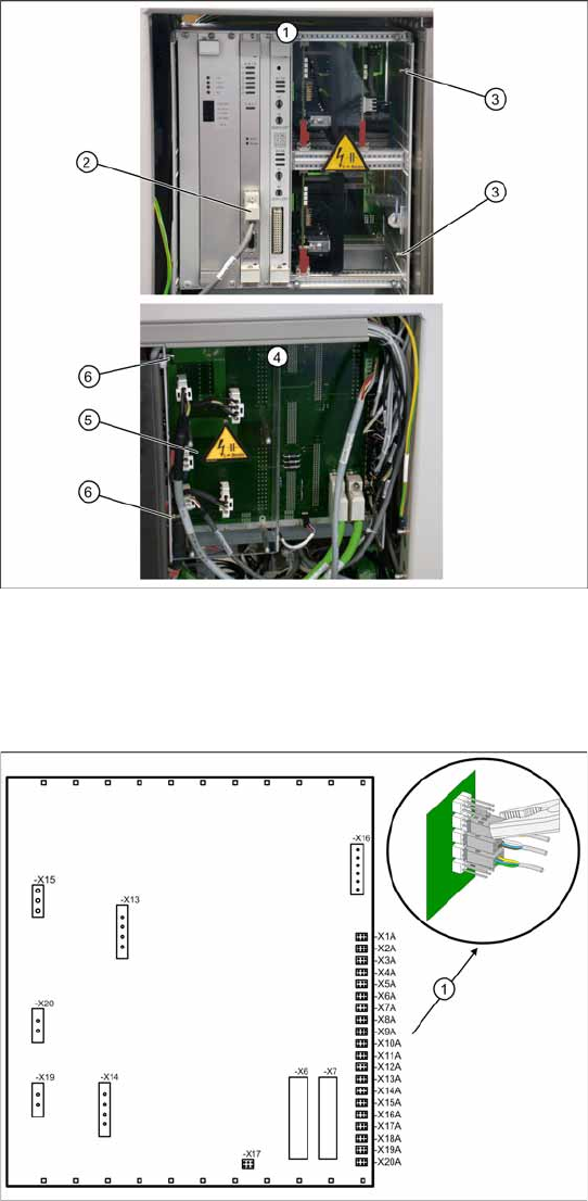
3.5.1.7 Replacing the Complete Control Unit [03047226-xx]
Overview
1. Control unit – front
2. CAN bus connection on controller board
3. 2 x cap nuts on the front
4. Control unit – back plane
5. Plexiglass cover
6. 2 x cap nuts on the back
Spare part
WPC control unit, compl. [03047226-01]
Removal
X Wear the ESD wristband.
X Loosen the 4 screws fastening the plexiglass
cover (5) to the back plane and remove this.
X Check whether all cables are labeled.
X Make sure that you are able to correctly assign
all cables and plugs. Where necessary, label
cables, plugs and connections for easier
reconnection later.
X Unplug the CAN bus cable from the front of the
controller board.
Control unit back plane – details
1. Connections for limit switches, sensors and
light barriers
X For connection details and complete circuit
diagrams, please refer to the following
documentation:
SIPLACE D1 detailed circuit diagrams
[00194841-xx] German
SIPLACE D1 detailed circuit diagrams
[00194841-xx] English
X Carefully unplug connections X1A to X20A on
the terminal strip (proximity switch, sensors
etc.) with a suitable pair of pliers (e.g.
combination pliers) (1). Make sure that you do
not bend the contact pins.
X Unplug the remaining cables, plugs and
connections.