00195346-0302_SM_WPC4_EN.pdf - 第40页
Replacing Spare Parts Control Unit and Power Supply Unit Power Supply U nit 40 Ser vice Manual SIPLACE WPC4 3.5.2.3 Removing the Front Cover Plate with Main Switch and the Emergency S top Button X Remove the sid e cover …
Replacing Spare Parts
Power Supply Unit Control Unit and Power Supply Unit
Service Manual SIPLACE WPC4
39
3.5.2.2 Replacing the Inrush current Limitation Board [03047752-xx]
The inrush current limitation board is located at the back of the electrical unit (see Section (3.5.2 Power
Supply Unit
J
38) ).
Spare part
Inrush current limitation board WPC4 [03047752-01]
Removal/installation
X Label all connections for easier installation later.
X Unplug all connections from the inrush current limitation board.
X Lever the inrush current limitation board off the mounting rail.
X Connect the new inrush current limitation board to the mounting rail and restore the electrical
connections.
Settings
There are no settings required.
Replacing Spare Parts
Control Unit and Power Supply Unit Power Supply Unit
40 Service Manual SIPLACE WPC4
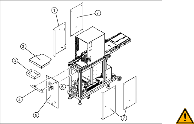
3.5.2.3 Removing the Front Cover Plate with Main Switch and the Emergency Stop Button
X Remove the side cover plate (1), in order to
access the power supply connections. If
necessary (depends on the service work to be
performed), you can also remove other side
covers (7).
X Loosen the 4 screws fastening the cover (2)
and remove this from the WPC4.
X Loosen the 2 screws fastening the service box
(3) and remove this from the WPC4. The
fastening screws on the handle (4) can now be
loosened from inside.
X Loosen the 2 screws on the inside of the
handle (4) and remove the handle.
WARNING: Voltage at cable to main
switch
When the WPC4 power cable is
connected and the main switch has
been turned off, voltage is still present
at the cable to the main switch, at the
mains filter and at the terminals to the
main switch.
X Disconnect the WPC4 from the
power supply.
X Check whether all cables are labeled(X1h to
X5h).
X Make sure that you will be able to correctly
assign all cables and plugs again. Where
necessary, label cables, plugs and
connections for easier reconnection later.
X Disconnect the cables (X1h to X5h) from the
installation plate of the power supply unit (6).
X Loosen the 4 fastening screws on the front
plate cover (5).
X The main switch and the emergency stop
button are now accessible for service
purposes.
X Loosen the ground terminal on the front plate
cover, if you need to remove the complete
front plate cover.
Replacing Spare Parts
Power Supply Unit Control Unit and Power Supply Unit
Service Manual SIPLACE WPC4
41
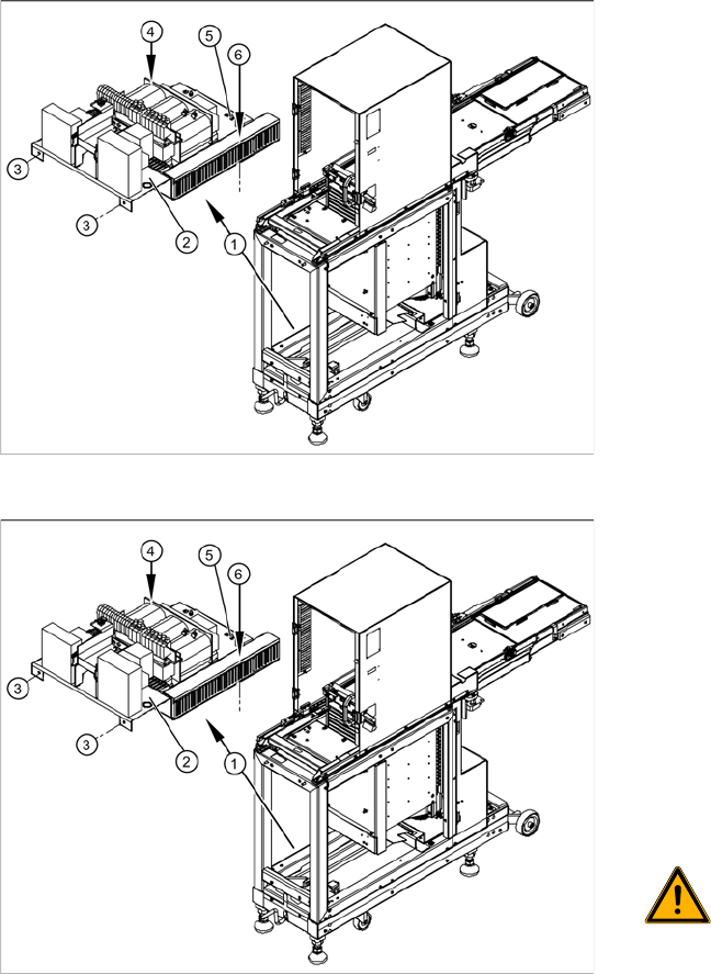
3.5.2.4 Replacing the Complete Power Supply Unit [03047298-xx]
X Remove all cable fixtures (cable ties etc.) and disconnect all cables and plugs from the power supply
unit.
X For connection details and complete circuit diagrams, please refer to the following documentation:
SIPLACE D1 detailed circuit diagrams [00194841-xx] German
SIPLACE D1 detailed circuit diagrams [00194841-xx] English
X Loosen the 4 fastening screws (3), (4) and (6).
X Disconnect the ground terminal (5) from the installation plate of the power supply unit.
X Remove the installation plate with the complete power supply unit from the WPC4, by pulling the
power supply unit out to the side.
X The power supply assemblies are now accessible for further service work, such as replacement of
the mains filter, rectifiers or transformers.
Overview
The power supply assemblies (1), such as the
transformer, relays and contactors, inrush current
limitation board etc. are fitted on an installation
plate (2) and can be removed as a complete unit.
The installation plate is fixed with 4 screws to the
WPC4 frame:
2 x side, front (3)
1 x on frame, left side (4)
1x on frame, right side - in cable duct (6)
Removal
X To gain better access to the power supply unit,
dismantle the side covers and, if necessary,
the front cover. See Section (3.5.2.3 Remo-
ving the Front Cover Plate with Main Switch
and the Emergency Stop Button
J
40) .
X Check whether all cables are labeled.
X Make sure that you are able to correctly assign
all cables and plugs again. Where necessary,
label cables, plugs and connections for easier
reconnection later.
WARNING: Voltage at cable to main
switch
When the WPC4 power cable is
connected and the main switch has
been turned off, voltage is still present
at the cable to the main switch, at the
mains filter and at the terminals to the
main switch.
X Disconnect the WPC4 from the
power supply.