00195346-0302_SM_WPC4_EN.pdf - 第55页
Replacing Spare Parts Replacing the Collision Light Barriers [03047281- xx] Limit Switche s, Sensors and Light Barriers Service Manual SIPLACE WPC4 55 3.6.8.1 Adjusting the Collision Light Barriers X Loosen the two faste…
Replacing Spare Parts
Limit Switches, Sensors and Light Barriers Replacing the Collision Light Barriers [03047281-xx]
54 Service Manual SIPLACE WPC4
X If necessary, correct the mechanical position of the limit switch and repeat the measurement
procedure.
X If the value is within the permissible limits, save the data by clicking on
Accept
.
X Seal the two mounting bracket fastening screws with locking varnish.
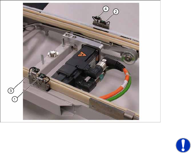
3.6.8 Replacing the Collision Light Barriers [03047281-xx]
Overview
1. Collision light barrier for normal components
(receiver) with LED
2. Collision light barrier for normal components
(transmitter)
3. Collision light barrier for high components
(transmitter)
4. Collision light barrier for high components
(receiver) with LED
Spare parts
Collision LB for normal components
[03047281-01]
Collision LB for high components [03047282-
01]
NOTE: Transmitter and receiver
together as one spare part
The transmitter and receiver of the
relevant collision light barrier are
stocked as one spare part with one part
number.
X Depending on the error occurring,
you may need to replace the
transmitter and receiver together.
Replacing Spare Parts
Replacing the Collision Light Barriers [03047281-xx] Limit Switches, Sensors and Light Barriers
Service Manual SIPLACE WPC4
55
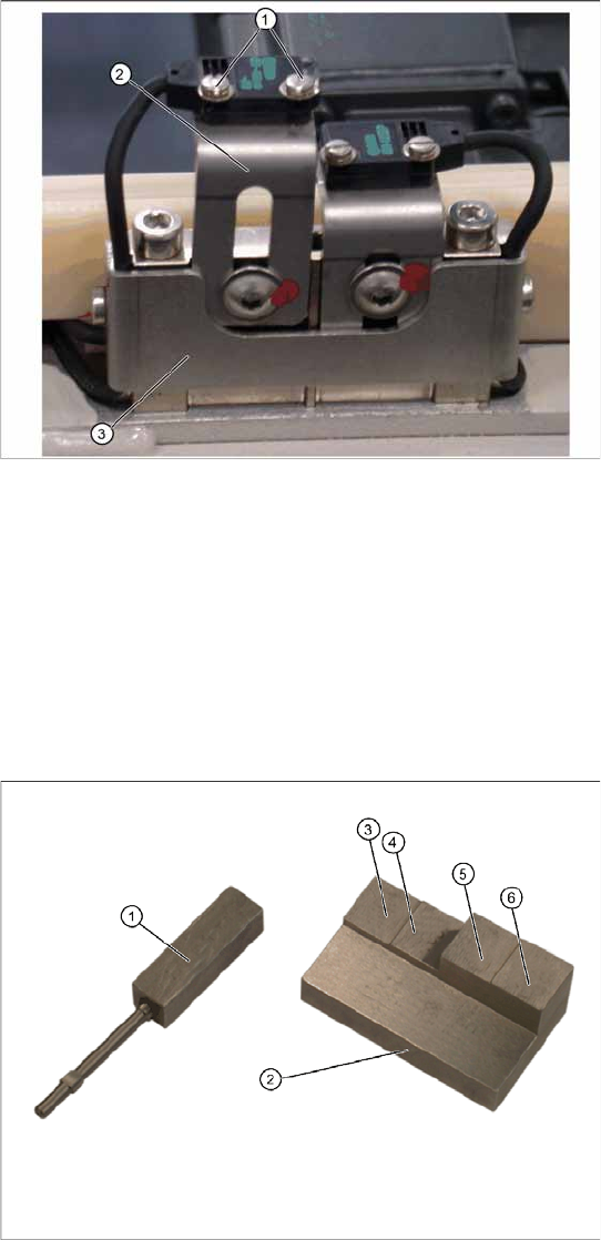
3.6.8.1 Adjusting the Collision Light Barriers
X Loosen the two fastening screws (1) for the
relevant sensor (transmitter or receiver) on the
mounting bracket (2).
X Loosen the two screws holding the cable
fixtures (3).
X You need to remove the plastic guidance on
the right-hand side, so that you can unthread
the plug or light barrier.
X Loosen the cable clamps and remove the
cable ties.
X Unthread the connection cable as far as the
control unit back plane and unplug it from the
terminal strip.
X Fit the sensor on the mounting bracket (2).
X Align the sensor parallel to the mounting
bracket (3).
X Restore the electrical connection and fix the
connection cable into place.
Settings
Set the collision light barriers. See Section (3.6.8.1
Adjusting the Collision Light Barriers
J
55) .
Tools and equipment
1. Setting gauge small [03052363-02]
2. Setting gauge large for collision lightbarriers
[03051814-01]
3. Step for passage height of "normal"
components in case that every level of the
WPC is used.
4. Step for trigger height of collision light barrier
for "normal" components
5. Step for passage height for "high" components
if the subsequent level above is not used.
6. Step for trigger height of collision lightbarrier
for "high" components
Replacing Spare Parts
Limit Switches, Sensors and Light Barriers Replacing the Collision Light Barriers [03047281-xx]
56 Service Manual SIPLACE WPC4
The status of the collision lightbarrier is displayed at the integrated LED
Red LED ON = not triggered (normal mode)
Red LED OFF = triggered (light beam is interrupted - collision situation)
Green LED ON = ready for operation/stability display (optimum light barrier setting)
Green LED OFF = ready for operation/stability display (no optimum light barrier setting)
X For the setting of the collision lightbarriers the large setting gauge (2) is needed.
Step 1: Height setting
X Put the setting gauge with the step for passage height on the WPTC in front of the corresponding
sender/receiver.
The green and the red LEDs must be ON.
X Move the gauge or the WPTC to the trigger height step.
X Check whether at the trigger height step the light beam is now interrupted:
The red LED must be OFF.
X If the setting is not correct the height of the sender or receiver at position (4) and (6) resp. (7) and
(8) must be corrected.
X Put the setting gauge with the step for trigger height on the WPTC in front of the corresponding
sender/receiver. The collision lightbarrier must definitely trigger here, too.
X Repeat the described procedure until the collision lightbarrier is adjusted to the correct height and
switches at the trigger points over the whole width of the WPTC.
Step 2: Functional check in SITEST
X Additionally check in SITEST if the correct outputs are switched.
In the SITEST main menue in
Function => SITEST Inputs-/Outputs
the display
collision
lightbarrier for normal components
or
collision lightbarrier for high components
will be
activated.
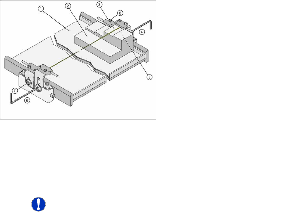
Measurement setup and procedure
1. Waffle pack tray carrier (WPTC)
2. Setting gauge
3. Passage height (for high components)
4. Setting of collision lightbarrier (receiver) for
high components
5. Step for trigger height of collision lightbarrier
for "high" components
6. Setting of collision lightbarrier (sender) for high
components
7. Setting of collision lightbarrier (receiver) for
normal components
8. Setting of collision lightbarrier (sender) for
normal components
NOTE:
X The settings must be set on both sides of the WPTC.
X Check the function in SITEST (Step 2)