00195346-0302_SM_WPC4_EN.pdf - 第60页
Replacing Spare Parts Limit Switches, Sensors and Light Ba rriers Replacing the Bottom Lifti ng Axis Limit Switch [03047280- 01-xx] 60 Ser vice Manual SIPLACE WPC4 3.6.1 1 Replacing the Bottom Lif ting Axis Limit Switch …
Replacing Spare Parts
Replacing the Top Lifting Axis Limit Switch [03047279-xx] Limit Switches, Sensors and Light Barriers
Service Manual SIPLACE WPC4
59
3.6.10 Replacing the Top Lifting Axis Limit Switch [03047279-xx]
Settings
X Check the function and correct position of the limit switch. The limit switch must switch when the
lifting axis moves over the switch (end position).
X To do this, open the SITEST main view and select the function=>
SITEST Settings
.
X In the input area
Axis,
select the radio button
Feed axis
.
X In the input area
Travel range
select the button
Limit switch -
.
The lifting axis will be moved so that an actuator on the lifting axis moves over the limit switch. The
limit (end position) will be calculated.
In the SITEST main view, function=>
SITEST inputs/outputs 1,
the display
Top lifting axis limit
switch
will be activated.
A dialog box will open and the calculated value will be shown. The permissible limits (minimum/
maximum position) will also be shown. The end position must be within these limits.
X Check the permissible limits against the value actually measured.
X If necessary, correct the mechanical position of the limit switch and repeat the measurement
procedure.
X If the value is within the permissible limits, save the data by clicking on
Accept
.
X Seal the two mounting bracket fastening screws with locking varnish.
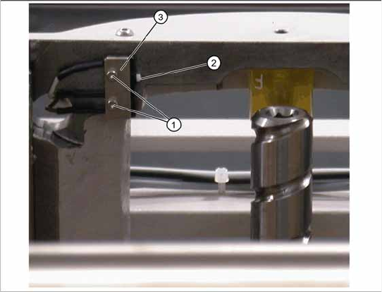
Spare part
Top lifting axis limit switch [03047279-01]
Removal/installation
X Mark the exact position of the limit switch.
X Loosen the two fastening screws (1) on the
limit switch.
X Remove the fixture plate (3).
X Loosen the cable clamps and remove the
cable ties.
X Unthread the connection cable as far as the
control unit back plane and unplug it from the
terminal strip.
X Fit the new limit switch.
X Fit the new limit switch with fixture plate (3) at
the marked installation position.
X Restore the electrical connection and fix the
connection cable into place.
Replacing Spare Parts
Limit Switches, Sensors and Light Barriers Replacing the Bottom Lifting Axis Limit Switch [03047280-01-xx]
60 Service Manual SIPLACE WPC4
3.6.11 Replacing the Bottom Lifting Axis Limit Switch [03047280-01-xx]
Settings
X Check the function and correct position of the limit switch. The limit switch must switch when the
lifting axis moves over the switch (3) (end position).
X To do this, open the SITEST main view and select the function=>
SITEST Settings
.
X In the input area
Axis,
select
Feed axis
.
X In the input area
Travel range
select
Limit switch +
.
The lifting axis will be moved so that an actuator on the lifting axis moves over the limit switch. The
limit (end position) will be calculated.
In the SITEST main view, function=>
SITEST inputs/outputs 1,
the display
Bottom lifting axis limit
switch
will be activated.
A dialog box will open and the calculated value will be shown. The permissible limits (minimum/
maximum position) will also be shown. The end position must be within these limits.
X Check the permissible limits against the value actually measured.
X If necessary, correct the mechanical position of the limit switch and repeat the measurement
procedure.
X If the value is within the permissible limits, save the data by clicking on
Accept
.
X Seal the two mounting bracket fastening screws with locking varnish.
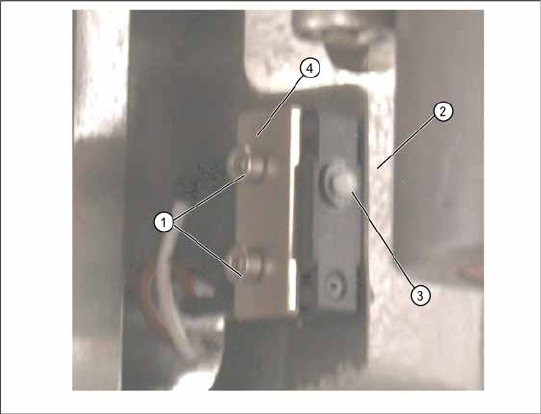
Spare part
Bottom lifting axis limit switch [03047280-01]
Removal/installation
X Move the lifting axis upwards into the refill
position. The limit switch is located in the
frame, under the lifting axis.
X Remove the front cover (on the lifting axis
drive motor). You can now access the opening
for the limit switch connection cable.
X Mark the exact position of the limit switch.
X Loosen the two fastening screws (1) on the
limit switch.
X Remove the fixture plate (4).
X Loosen the cable clamps and remove the
cable ties.
X Unthread the connection cable as far as the
control unit back plane and unplug it from the
terminal strip.
X Fit the new limit switch with fixture plate (4) at
the marked installation position.
X Align the limit switch parallel to the stopper
edge (2).
X Restore the electrical connection and fix the
connection cable into place.
Replacing Spare Parts
Replacing the Safety Switch [03048181-xx] Limit Switches, Sensors and Light Barriers
Service Manual SIPLACE WPC4
61
3.6.12 Replacing the Safety Switch [03048181-xx]
The connection cable has two separate connections:
Unplug the connection cable at terminal strip x12a on the control unit back plane.
Unplug the connection cable from the safety loop.
X Fit the new safety switch at the marked installation position.
X Restore the electrical connection and fix the connection cable into place.
Settings
X Make sure that the door contact engages properly. If necessary, correct the installation position at
the slots.
X Check that the safety switch switches reliably at the docked WPC4.
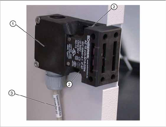
Spare part
X Safety switch, closed (safety switch with
cable) 03048181-xx]
Removal/installation
X Mark the installation position of the safety
switch (1) at the two fastening screws (2) with
slots.
X Loosen the two fastening screws (2) and
remove the safety switch (1).
X Unthread the connection cable (3) as far as the
control unit back plane.