00195346-0302_SM_WPC4_EN.pdf - 第63页
Calibration and Settin gs Procedure - Calibrating the Lifting Axis Lifting Axis Service Manual SIPLACE WPC4 63 4 Calibration and Settings 4.1 Lif ting Axis 4.1.1 Procedure - Calibrating the Lif t ing Axis
Replacing Spare Parts
Limit Switches, Sensors and Light Barriers Replacing the Safety Switch [03048181-xx]
62 Service Manual SIPLACE WPC4
Calibration and Settings
Procedure - Calibrating the Lifting Axis Lifting Axis
Service Manual SIPLACE WPC4
63
4 Calibration and Settings
4.1 Lifting Axis
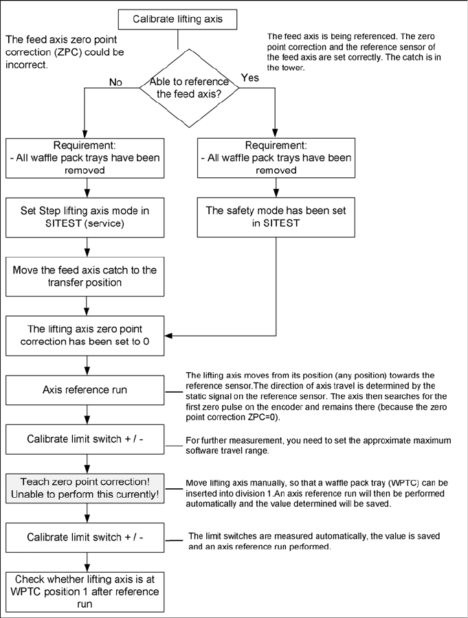
4.1.1 Procedure - Calibrating the Lifting Axis
Calibration and Settings
Lifting Axis Calibrating the Reference Sensor, Lifting Axis
64 Service Manual SIPLACE WPC4
4.1.1.1 Troubleshooting for "Teach Zero Point Correction"
4.1.2 Calibrating the Reference Sensor, Lifting Axis
See the service manual (3.6.9 Replacing the Reference Sensor, Lifting Axis [03047278-xx]
J
57) .
Description - solution
When teaching the zero point correction, move the
lifting axis manually, so that a waffle pack tray
carrier can be inserted. The feed axis needs to be
in the transfer position for this.
This does not function with the current station
software 603.
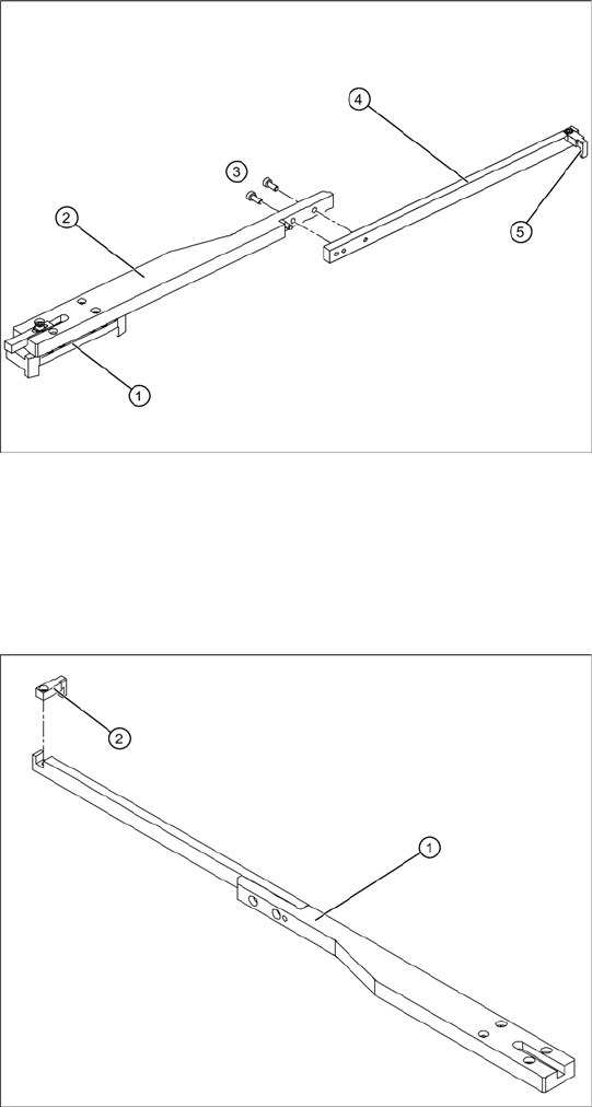
When using split catches, you need to dismantle
the catch extension, in order to move the lifting
axis.
Dismantling the catch extension on split
drivers
1. Guide trolley
2. Catch clamping unit
3. 2 fastening screws
4. Catch extension
5. Catch
Dismantling the catch lug
In another version of the WPC4, the catch is not
split.
X If a calibration run is required for this WPC4,
you will need to dismantle the lug (2) on the
catch (1).