KE2020-Instruction-Manual-ver1.30.pdf - 第363页
5 − 21 ⑪ Contrast Set the “cont rast between a pin (ball) and m olding section of a BG A component”, or set t he “recog nition patter n f or an outline-r ecognized component”. 1) For a BGA • Setting items T able 5.5.3.1 …
5 − 20
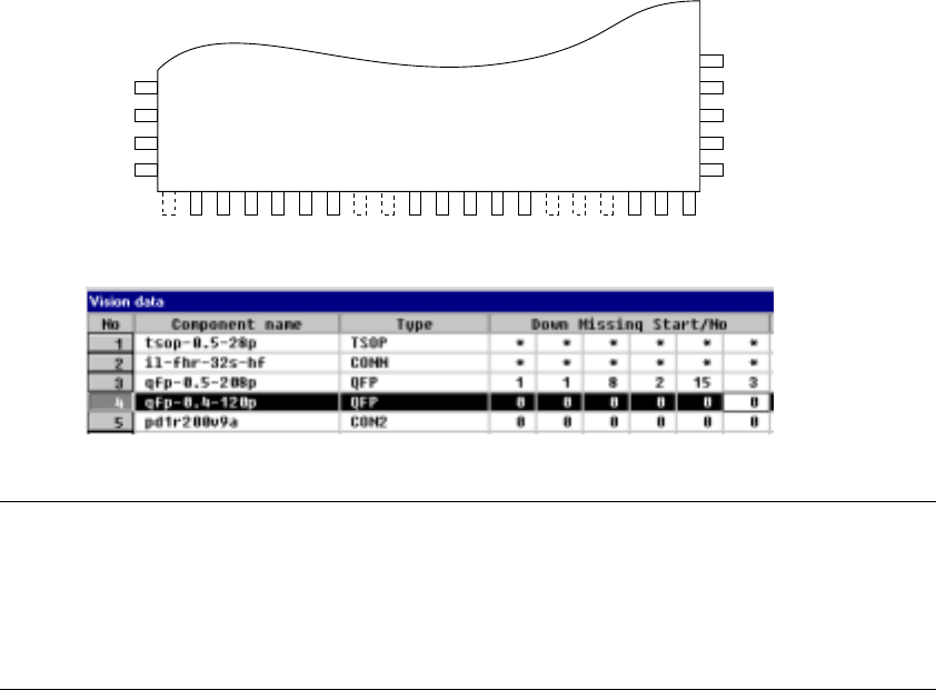
• The following Figure 5.2.3.10.2 shows a QFP component whose bottom side
has a missing lead(s).
<Example> Missing pins on the bottom side: Pins 1, 8, 9, 15, 16 and 17
1234567891011121314151617181920
Enlarged bottom view of QFP
1 pin from pin 1. 2 pins from pin 8. 3 pins from pin 15.
Figure 5.2.3.10.2 Lead setting example
Notes
①
For a BGA component, specify the number of missing balls located on the
outer frame only.
②
For a BGA component, the missing balls should be viewed from the bottom
(rear), then set.
5 − 21
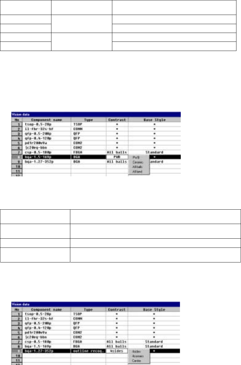
⑪ Contrast
Set the “contrast between a pin (ball) and molding section of a BGA
component”, or set the “recognition pattern for an outline-recognized
component”.
1) For a BGA
• Setting items
Table 5.5.3.1
Selection on the
pop-up menu
Recognition range Type
PWB PWB type whose molding section looks black
Ceramic
Recognizes balls on the
outer frame only.
Ceramic type whose molding section looks white
All balls Ball recognition by a pattern
All land
Recognizes all balls of a
component.
All land recognition of an LGA
If you change the setting of this item to “PWB” or “Ceramic” after you
select “All balls” or “All land” and set a ball pattern, the ball pattern is
initialized.
• How to set
When you click this setting item with the right button, the selection
pop-up menu appears on the screen.
2) For an outline-recognized component
• Setting items
Table 5.2.3.2
Selection on the pop-up
menu
Recognition method
4sides
Recognizes a component with four sides of a rectangle. This setting is
effective for a rectangle component whose corner is unclear.
4corners Recognizes a component with four corners of a rectangle.
Center
Recognizes a component by calculating the center of the substance which
is currently being shot.
• How to set
When you click this setting item with the right button, the selection
pop-up menu appears on the screen.
5 − 22
3) Limitation on components depending on the recognition method
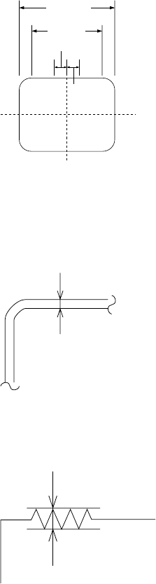
(A) Side recognition
Recognition conditions:
① Components whose whole shape is a rectangle or regular square
② Components whose linear portion (line segment) of a side is 1/2 or more of
the component outline size but whose linear portion (line segment) should
be 3 mm or more
③ Components whose side middle section is straight: 1.5 cm on both sides of
the center.
1.5 mm
1.5 mm
Line
segment
Component
outline size
④ Components whose component angle is within 90° ± 0.5°.
⑤ Components whose sides are 0.3 mm or more when their insides are
imaged darkly at imaging
0.3mm or more
⑥ Components whose side roughness forming a linear portion is 0.1 mm or
less
0.1mm or less
⑦ Components whose component shape is not convex.
When the above conditions are satisfied, side recognition is enabled.
Fig. 5.2.3.11-1 Explanatory Drawing of
Recognition Conditions 1), 2) and 3)
Fig. 5.2.3.11-2 Explanatory Drawing of
Recognition Condition 5)
Fig. 5.2.3.11-3 Explanatory Drawing of
Recognition Condition 6)