KE2020-Instruction-Manual-ver1.30.pdf - 第402页
5 − 60 Element group name First element position Layout inspection (Dimension) Missing elements Element Element offset Element size Element shape Cutting Lead size ELG0001 X:-7.25 Y : -5.1 Z: 0 θ : 0 To l e r a n c e : A…
5 − 59
⑪ Lead size
For a gullwing lead, enter the lead foot size here.
The “lead foot size” indicates the portion of a gullwing lead which is in contact
with a board.
- In the example, the length of a gullwing lead foot is 0.5 mm.
Enter the following values:
Width: 0.2 (same as the lead width)
Length: 0.4
♦ - Here, you have finished entering element data. When you click the <OK>
button displayed on the lower right corner, the “Element Group” screen
reappears.
- You have finished defining the first element group. When you click the
<OK> button displayed on the lower right corner, the “Extended Vision”
screen reappears.
• When you have the next element group to be defined at this point, click the <Add>
button to define the element group by entering data in the same manner.
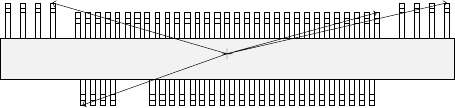
In the example, there are four element groups. Define four element groups.
All data to be entered is shown below:
Figure 5.2.4.4.10
Top View
Forth element group
(X, Y): (- 9.50, 5.1) mm
Theta: 180 degrees
Pitch: 0.5 mm, Count: 4
Lead length: 1.2 mm
Lead width: 0.4 mm
Gullwing lead: Flat
Foot length: 0.6 mm
Foot width: 0.4 mm
Third element group
(X, Y): (7.5, 4.9) mm
Theta: 180 degrees
Pitch: 0.5 mm, Count: 31
Lead length: 1.0 mm
Lead width: 0.2 mm
Gullwing lead: Flat
Foot length: 0.4 mm
Foot width: 0.2 mm
Second element group
(X, Y): (13.31, 5.1) mm
Theta: 180 degrees
Pitch: 1.27 mm, Count: 4
Lead length: 1.2 mm
Lead width: 0.4 mm
Gullwing lead: Flat
Foot length: 0.6 mm
First element group
(X, Y): (- 7.25, - 5.1) mm
Theta: 0 degrees
Pitch: 0.5 mm, Count: 30
Missing leads: three from
the fifth lead
Lead length: 1.0 mm
Lead width: 0.2 mm
Gullwing lead: Flat
Foot length: 0.4 mm
Foot width: 0.2 mm
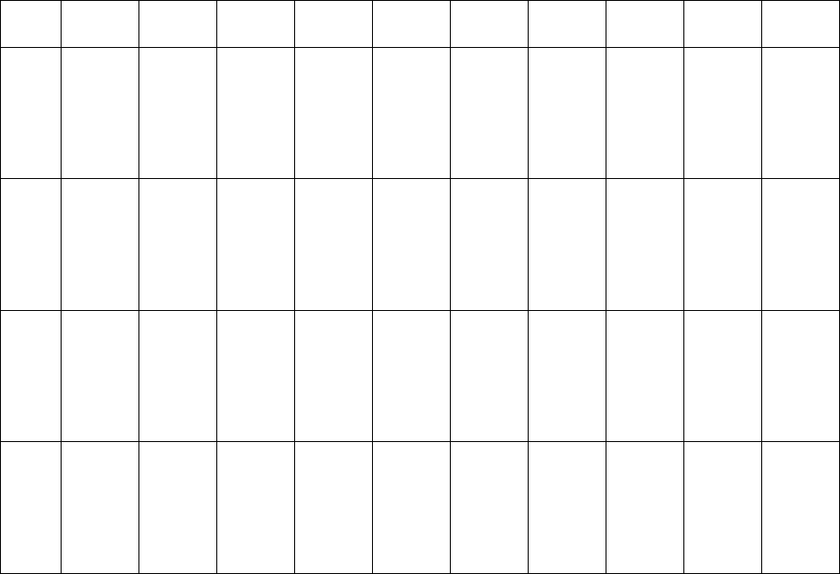
5 − 60
Element
group
name
First
element
position
Layout
inspection
(Dimension)
Missing
elements
Element
Element
offset
Element
size
Element
shape
Cutting Lead size
ELG0001 X:-7.25
Y: -5.1
Z: 0
θ: 0
Tol er anc e:
All set to 0.
√ 25% √ ID
Count of
Column: 30
Pitch of
Column:
0.5
Tolerance:
0
Start: 5
Count: 3
Type: Outer
Lead
Reference
pos.:
Center of the
bottom
Polarity:
Bright
Offset: all
set to 0.
Tolerance:
all set to 0.
Size
X: 0.2
Y: 1.0
Tolerance:
all set to 0.
Profile:
Gullwing
Cut shape:
Flat
Coating:
Bare
Cut width:
0
Cut length:
0
Size
X: 0.2
Y: 0.4
Tolerance:
all set to 0.
ELG0002 X: 13.31
Y: 5.1
Z: 0
θ: 180
Tol er anc e:
All set to 0.
√ 25% √ ID
Count of
Column: 4
Pitch of
Column:
1.27
Tolerance:
0
Type: Outer
Lead
Reference
pos.:
Center of the
bottom
Polarity:
Bright
Offset: all
set to 0.
Tolerance:
all set to 0.
Size
X: 0.4
Y: 1.2
Tolerance:
all set to 0.
Profile:
Gullwing
Cut shape:
Flat
Coating:
Bare
Cut width:
0
Cut length:
0
Size
X: 0.4
Y: 0.6
Tolerance:
all set to 0.
ELG0003 X: 7.5
Y: 4.9
Z: 0
θ: 180
Tol er anc e:
All set to 0.
√ 25% √ ID
Count of
Column: 31
Pitch of
Column:
0.5
Tolerance:
0
Type: Outer
Lead
Reference
pos.:
Center of the
bottom
Polarity:
Bright
Offset: all
set to 0.
Tolerance:
all set to 0.
Size
X: 0.2
Y: 1.0
Tolerance:
all set to 0.
Profile:
Gullwing
Cut shape:
Flat
Coating:
Bare
Cut width:
0
Cut length:
0
Size
X: 0.2
Y: 0.4
Tolerance:
all set to 0.
ELG0004 X: -9.5
Y: 5.1
Z: 0
θ: 180
Tol er anc e:
All set to 0.
√ 25% √ ID
Count of
Column: 4
Pitch of
Column:
1.27
Tolerance:
0
Type: Outer
Lead
Reference
pos.:
Center of the
bottom
Polarity:
Bright
Offset: all
set to 0.
Tolerance:
all set to 0.
Size
X: 0.4
Y: 1.2
Tolerance:
all set to 0.
Profile:
Gullwing
Cut shape:
Flat
Coating:
Bare
Cut width:
0
Cut length:
0
Size
X: 0.4
Y: 0.6
Tolerance:
all set to 0.
Click the <OK> button at the lower left corner of the screen after you define all element groups to finish the “Extended Vision”
data entry.
5 − 61
5.2.4.4.2 Ball components (Element group/Element format)
■ This section describes the procedure for creating data on ball components
(complex array components).
1. Operation on the “Extended Vision” screen
- Select “Ball Component” from the “Component Type” combo box.
- Check the “Element group/Element format” check box in the “Define data
format” field.
- Click the <Add> button on the “Element Group List”.
2. Operation on the “Element Group” screen
Define an element group.
An element group consists of components whose size and pitch is the same as
each other.
A complex array component refers to an area array component whose size is
different or whose ball/land pitch is different from each other.
When the lead pitch is not the same even though the polarity is the same, set
element groups separately. If the polarity is the same, the size and shape of the
polarity is the same also.
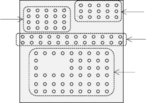
In the example shown in Figure 5.2.4.4.11, a complex array component that
consists of four element groups is shown.
• The procedure for creating data on this component is to be described below.
The element size and pitch of the second and third element groups are the
same as each another. However, columns of elements are not aligned with
each another. Define them as two different element groups.
The posture of a complex array component is viewed from the bottom in the
same manner as an area array component such as a BGA and FBGA.
Figure 5.2.4.4.11
Bottom View
Third element group
Fourth element group
Second element group
First element group