KE2020-Instruction-Manual-ver1.30.pdf - 第43页
1 − 34 1.2.4 Head-related unit: parts identification The head unit consist s of t he laser align sensor used to detect placement and ang le off sets of the com ponent, and t he Z slide shaft which can be moved up and dow…
1 − 33
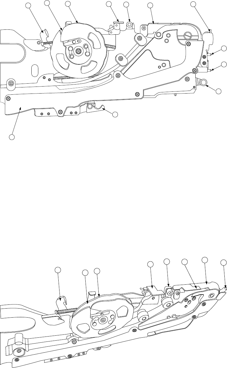
FF05/08 Parts identification (2/2)
12
11
16
17
4
5
15
13
7
2
1
10
Figure 1.2.3.6 Detailed illustration of the right side
①
X axis reference pin A
⑧
Stopper
⑮
Guide cover
②
X axis reference pin B
⑨
Free link
⑯
Unreeling plate
③
Sprocket wheel
⑩
Tape holder
⑰
Unreeling guide roller
④
Upper cover
⑪
Cover tape fixing plate
⑱
Reel support
⑤
Upper cover hook
⑫
Lock release lever
⑲
Tape groove
⑥
Shutter
⑬
Lock holder
⑦
Knock lever
⑭
Tape guide
12
11
10
16
17
5
6
4
Figure 1.2.3.7 Detailed illustration of the top side
1 − 34
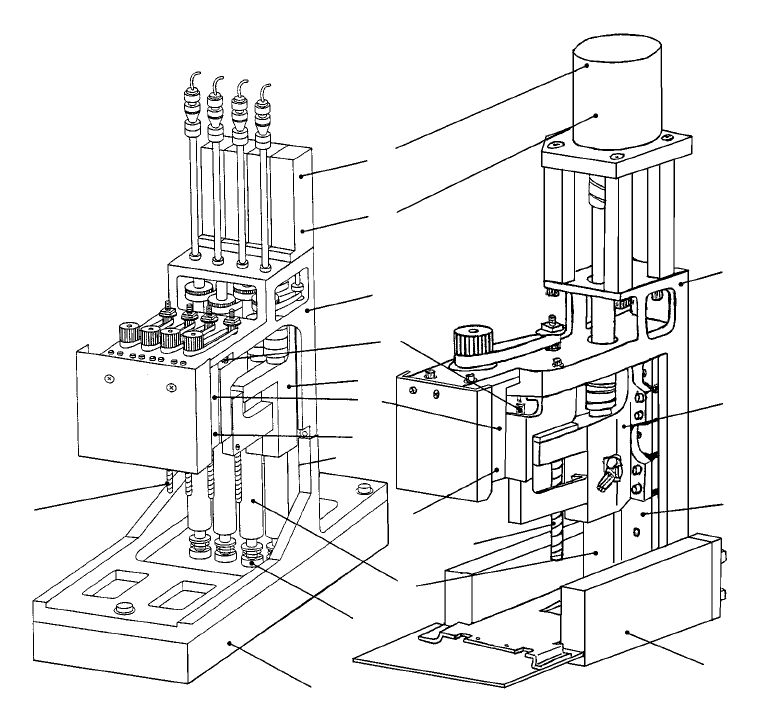
1.2.4 Head-related unit: parts identification
The head unit consists of the laser align sensor used to detect placement and angle
offsets of the component, and the Z slide shaft which can be moved up and down, or
be turned.
The Z slide shaft and the Z slide bracket of the Z axis are driven with rotations of the
ball screw.
The θ-axis encoder located on the upper section of the θ-axis motor detects the angle
of a component.
The machine is equipped with two units of MNLA head and FMLA head as standard
parts.
L Head-related unit (MNLA head) R Head-related unit (FMLA head)
Figure 1.2.4.1 Head-related unit
① Nozzle outer ⑦ θ-axis encoder
② Laser alignment sensor ⑧ Ball screw
③ Z-axis motor ⑨ Linear way
④ Z-axis encoder ⑩ Head-up spring
⑤ Z slide shaft ⑪ Head top bracket
⑥ θ-axis motor ⑫ Z slide bracket
⑦
⑥
⑪
⑪
⑫
⑨
②
②
①
⑤
⑧
④
④
⑨
③
⑫
⑩
⑧
1 − 35
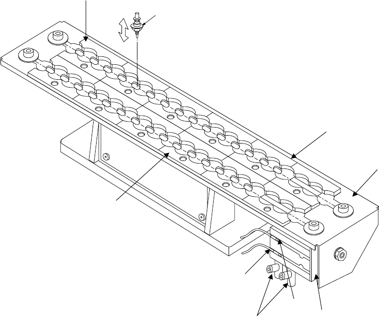
1.2.5 ATC unit (Automatic tool changer): parts identification
The slide plate w is opened and closed by the air cylinder ④ to store or
attach/detach the nozzle ⑨. The ATC OPEN sensor ⑥ and the ATC CLOSE
sensor ⑦ detect whether the slide plate ② is opened or closed, and the speed
controller ⑤ adjusts the speed for opening or closing the slide plate.
1
5
6
8
7
9
10
11
12
4
3
2
13
15
14
16
20
21
23
22
24
25
26
27
19
18
17
28
30
29
Figure 1.2.5
① ATC bracket ⑥ ATC OPEN sensor
② Slide plate ⑦ ATC CLOSE sensor
③ Nozzle outer support ⑧ ATC numbers (1 to 30, A, B)
④ Air cylinder ⑨ Nozzle
⑤ Speed controller
①
⑦
③
④
②
⑧
⑤
⑥
⑨