Nordson_EFD_Series_400_Instructions.pdf - 第5页
Series 400 Autovalve | Instructions / Parts Lists 5 www.nordsonefd.com info@nordsonefd.com +1-401-431-7000 Sales and service of Nordson EFD dispensing systems are available worldwide. P/N Ref. # Qty. Description 7702008 …
Series 400 Autovalve | Instructions / Parts Lists
4 www.nordsonefd.com info@nordsonefd.com +1-401-431-7000 Sales and service of Nordson EFD dispensing systems are available worldwide.
Maintenance
Disassembly and Cleaning
1. Remove the manifold and seat plate (8). Pry bar slots are provided.
2. Remove the air cylinder bolts (2) and wiggle the air cylinder apart.
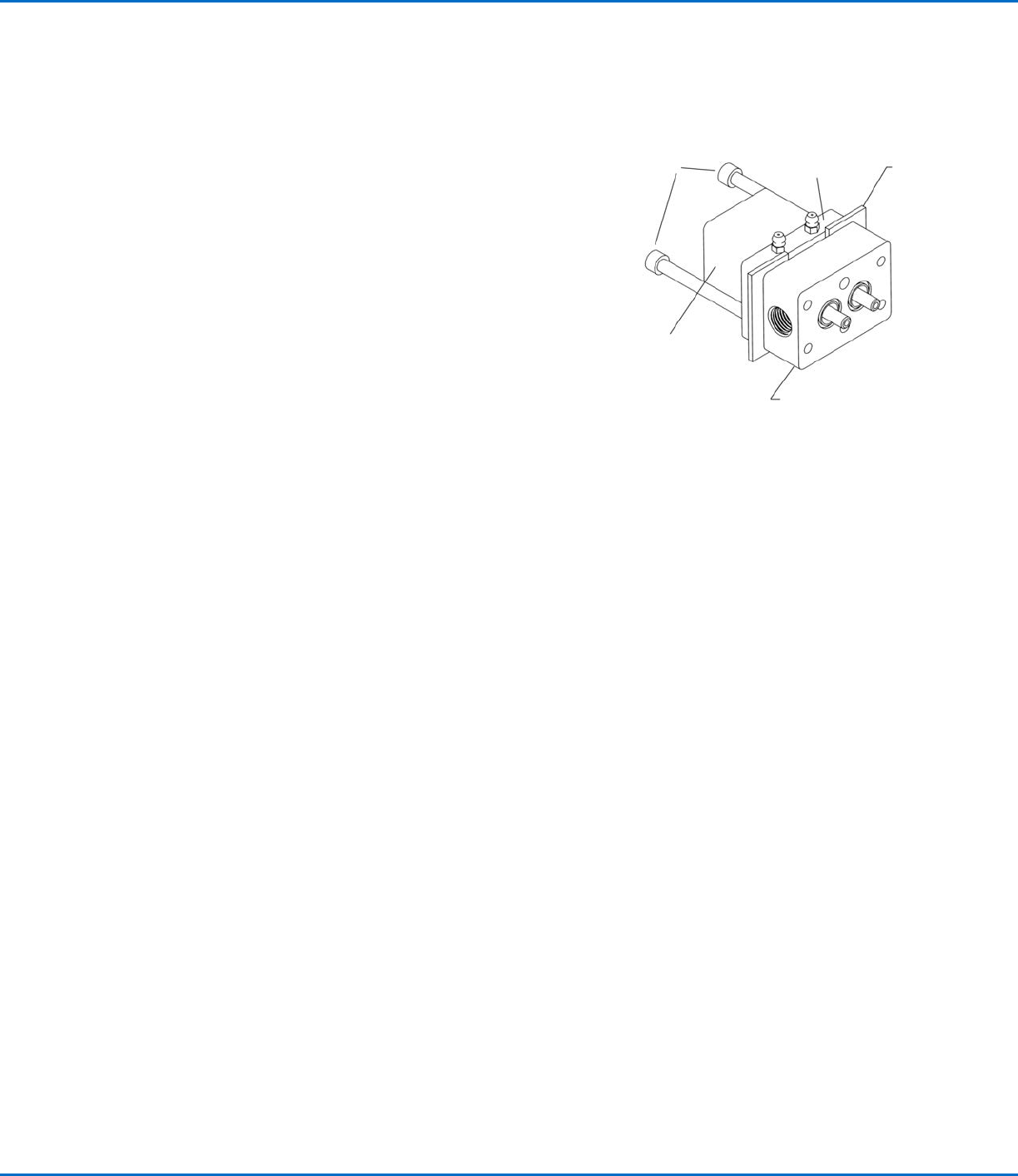
If the assembly is frozen, use the pry bar slots on the valve body
(7) to separate the valve body (7) from the tie plate (5). Insert flat
pieces of metal between the valve body and the tie plate as per
Figure 1. Thread the manifold screws (36) into the back of the tie
plate and push the valve body apart. Apply uniform pressure to
prevent the body from cocking and bending the air cylinder shafts
(75).
3. Once apart, the parts should be cleaned. We recommend
overnight soaking in suitable solvent. All parts can be soaked
except the handle and air cylinder.
Manifold
screws
Tie plate
Metal
plate
Air cylinder
Valve body
Figure 1
Rebuilding the Autovalve
1. After cleaning, inspect the following components:
a. Seat plate (8) on sealing surface
b. Manually retract and extend the shafts (75) from air cylinder (1).
c. If the optional handle is used, connect air into the inlet and check 4-way action of cartridge valve (103).
2. Refer to page10 for a repair kit which contains lip seals, O-rings, and front seals.
3. Lubricate lip seals (3) and shafts (75) with auto grease (read SDS prior to use).
4. Insert four back lip seals (3): two into tie plate (5) and two into the valve body (7). The lip seals are two pieces: an O-ring
and a U-cup. They should always be installed with the O-ring facing the material inlets (body of the valve).
5. Push the air cylinder (1) thru the tie plate (5) and the valve body (7) and engage the screws (2).
6. Push front seal (13) and washer (12) onto adjustment screw (14). To prevent binding, apply auto grease to the threads on
the adjustment screws (14). Thread the seal and adjustment screw assembly into air cylinder shafts.
7. Assemble the seat plate (8) onto the valve body (7).
Final QC Check
Before the manifold is assembled, we recommend air be connected to the air cylinder (1) and the open / close function of the
front seals (13) be inspected for leakage.
The front seals cold flow into the proper shape as the valve is used. It may be necessary to pressurize the air cylinder, but not
the A & B fluids.
Series 400 Autovalve | Instructions / Parts Lists
5www.nordsonefd.com info@nordsonefd.com +1-401-431-7000 Sales and service of Nordson EFD dispensing systems are available worldwide.
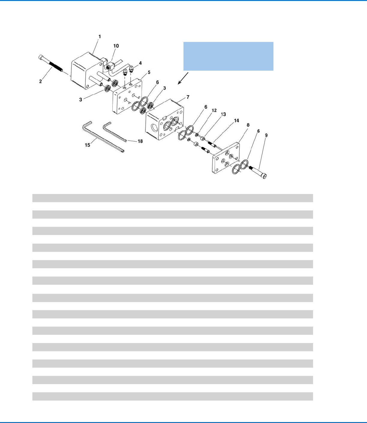
P/N Ref. # Qty. Description
7702008 1A 1 Single Air Cylinder with Hardened SS Shafts
7702016 1B 1 Double Air Cylinder with Hardened SS Shafts (not shown)
7702295 2A 2 SHCS 10-24 x 2" long for Single Air Cylinder 450 Valve
7702325 2B 2 SHCS 10-24 x 3" long for Double Air Cylinder (not shown)
7702266 3A 4
Lip Seal: Viton
®
U-Cup and Viton O-ring
7702281 3B 4 Lip Seal: PU U-Cup and Viton O-ring
7702280 3C 4 Lip Seal: PTFE U-Cup and PTFE O-ring
7702277 3D 4 Lip Seal: UHMPE U-Cup and SS Spring
7702268 4 2 Grease Fitting, 10-32
7702270 5 1 Aluminum Tie Plate
7702813 6A 6 Viton O-ring
7702810 6B 6 EP O-ring
7702275 6C 6 PTFE Encapsulated O-ring
7702019 7A 1 Alum Body 9/16-18 Inlet Ports for 400 Valve
7702025 7B 1 SS Body 9/16-18 Inlet Ports for 400 Valve
7702026 8A 1 Stainless Steel Seat Plate for 400 Valve
7702028 9 2 Stainless Steel SHSS 1/4" Dia x 1" long for 400 Valve
7702297 10 2 Assembled Air Tube and Fitting 10-32 Thread
7702010 12A 2 Stainless Steel Washer for 400 Valve
7702011 13A 2 Front Seal for 400 Valve
7702012 14 2 Stainless Steel Adjustment Screw for 400 Valve
7702014 15 1 Adjustment Screw Driver for 400 Valve
7702364 16 1 Auto Grease Cartridge 3 oz (not shown)
7702373 17 1 Grease Gun
7702017 18 1 1/8" Short Arm Hex Key
Maintenance (continued)
NOTE: The O-rings in the lip seals face
the body (item 7). Consult factory for
additional seal combinations.
Series 400 Autovalve | Instructions / Parts Lists
6 www.nordsonefd.com info@nordsonefd.com +1-401-431-7000 Sales and service of Nordson EFD dispensing systems are available worldwide.
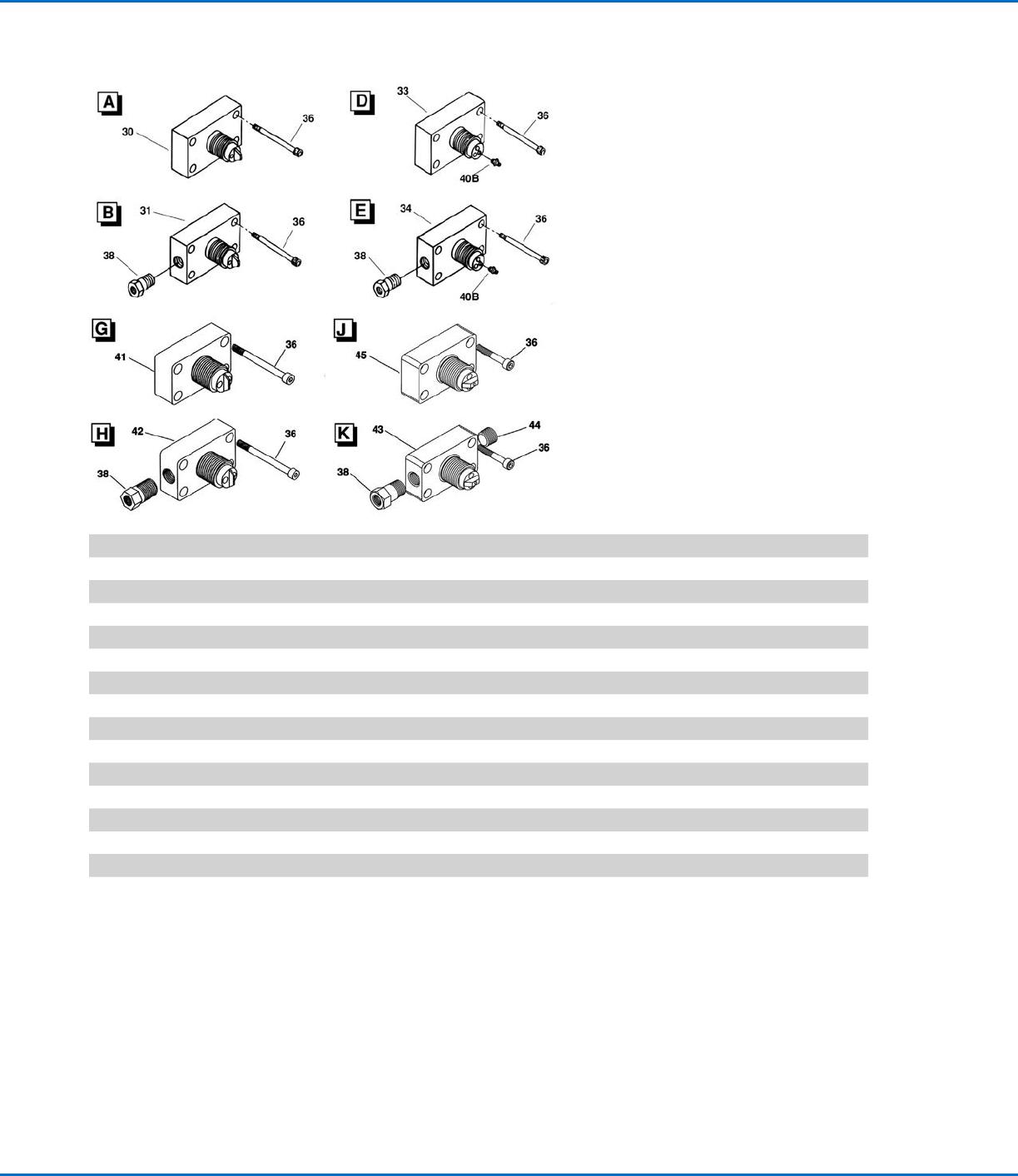
P/N Ref. # Qty. Description
7702292 30A 1 Alum Manifold/160 Series 7/8-14 Thread, 1:1 Ratio
7702293 30B 1 SS Manifold/160 Series 7/8-14 Thread, 1:1 Ratio
7702322 31A 1 Alum Manifold/160 Series 7/8-14 Thread, 1:1 Ratio with 1/4 NPT Solvent Port
7702349 33A 1 Alum Manifold/160 Series 7/8-14 Thread, Wide Ratio
7702294 36 4 SHCS 10-24 x 2 1/2" long for 450 Manifold
7702492 38A 1 Check Valve: Brass Solvent Flush
7702494 38B 1 Check Valve: Stainless Steel Solvent Flush
7702327 40A 1 Polypropylene fitting, 10-32 with 0.09" orifice
7702328 40B 1 Polypropylene fitting, 10-32 with 0.06" orifice
7702329 40C 1 Polypropylene fitting, 10-32 with 0.04" orifice
7702033 41A 1 Alum Manifold/160 Series 7/8-14 Thread, 1:1 Ratio, High Flow
7702035 42A 1 Alum Manifold/160 Series 7/8-14 Thread, 1:1 Ratio, High Flow with 1/4 NPT Solvent Port
7702525 44A 1 1/4 NPT Plug
7702554 44B 1 SS 1/4 NPT Plug
7702049 45A 1 Alum Manifold/160 Series 7/8-14 Thread, Wide Ratio, High Flow
Additional Manifolds available upon request:
• 1/2 MNPT*
• 30 ppm & 60 ppm flow rates for foam applications*
*These manifolds will not accept our 160 Series nozzles.
Manifolds for Series 160 Disposable Mixers