Specification_SIPLACE_S23HM_eng.pdf - 第11页
10 Restricti ons for Bar Code R eading of PCB Sizes 460 x 460 mm Description S S S Si i i in n n ng g g gl l l le e e e c c c co o o on n n nv v v ve e e ey y y yo o o or r r r The SIPLACE PCB bar code scan- ner supports…
9
Description
The demands for a precise sub-
strate centering are becoming
more stringent due to the increas-
ing use of ceramic substrates in
the Flip Chip technology. This
challenge is met by the optical and
mechanical ceramic substrate cen-
tering on the SIPLACE S-23 HM
and SIPLACE 80 F
4
.
As with the PCB vision module,
the optical centering is conducted
with the aid of reference marks.
Depending on the contrast ratio
the machine activates the standard
lighting or the oblique lighting con-
tained in option:
On ceramic and CM blue light
(Item No 116172).
On flexible PCBs using vision
module without IF-filter infrared
light (Item No 116173).
In specific case a mechanical cen-
tering is required, e.g., when
placement is to be to the edge of
the substrate, handling of the sub-
strate edges is to be particularly
gentle or substrates are scribed.
With this gentle, bounce-free ap-
proach the substrate is fixed in the
Y-direction between a stop bar and
a rocking lever. In the X-direction it
is centered pneumatically.
PCB Conveyor:
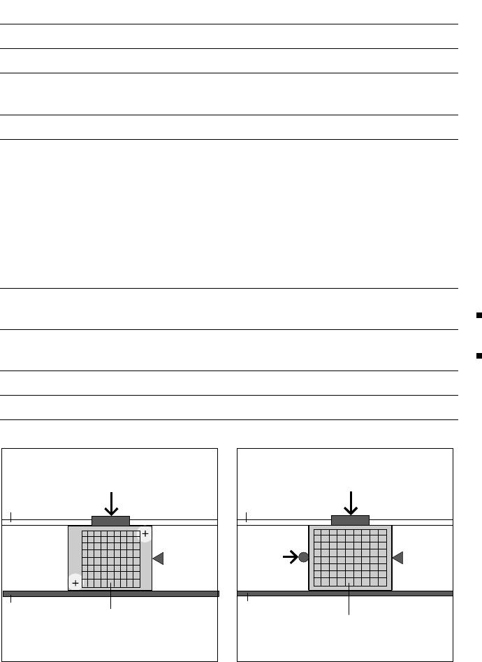
Ceramic Substrate Centering (Option)
Technical Data
Substrate dimensions 2" x 2" to 4" x 7"
Substrate thickness 0.5 to 1.5 mm
Substrate model Unscribed (no problems)
Scribed (after test)
Contact in conveyor 2.5 mm
Optical centering:
Field of view of PCB
vision module
Type of light:
with light pastes
with dark pastes and little
distance to neighboring struc-
tures (> 1 mm)
5.7 mm x 5.7 mm
PCB vision module (standard)
Oblique lighting (option)
Reference mark criteria See PCB Vision Module Position
Recognition
Mechanical centering:
X-/Y-axis centering accuracy
± 0.07 mm / 4 s
Clearance under substrate 12 mm
Compressed air connection 5.5 bar
Optical Centering via Mechanical Centering
PCB Camera
Movable
Transport Side
Y-Fixation
Y-Fixation
Fixed
Transport
Side
Stopper
Stopper
Ceramic Substrate
Ceramic Substrate
Movable
Transport Side
X-Center-
ing
Fixed
Transport
Side
10
Restrictions for Bar Code Reading
of PCB Sizes 460 x 460 mm
Description
S
SS
Si
ii
in
nn
ng
gg
gl
ll
le
e e
e c
cc
co
oo
on
nn
nv
vv
ve
ee
ey
yy
yo
oo
or
rr
r
The SIPLACE PCB bar code scan-
ner supports the flexible manufac-
ture of SMD products and en-
hances placement reliability. It
recognizes all types of cost in gen-
eral use in industry.
The laser scanner reads the bar
code label on the top or bottom of
each PCB while it is being trans-
ported in. On the basis of the bar
code data the line computer auto-
matic selects the correct place-
ment program from the bar code
allocation list previously prepared
and sends it to the station. Once a
bar code filter has been defined,
only the data in the bar code which
has been marked as being relevant
is compared. This procedure is
performed in slack time while a
PCB already in the machine is be-
ing populated. If a number of PCBs
with the same bar code are moved
in one after the other, the program
is only transferred the first time.
The following preconditions apply
for all products which are to be
manufactured with the aid of the
PCB bar code:
identical component set-up on
the individual machines in the
line
all of the PCBs are the same
width.
D
DD
Du
uu
ua
aa
al
l l
l c
cc
co
oo
on
nn
nv
vv
ve
ee
ey
yy
yo
oo
or
rr
r
With a dual conveyor, the sole
purpose of the PCB bar code is to
relay the bar code via a GEM inter-
face. This is imperative for utiliza-
tion. Automatic placement pro-
gram supply is not possible.
PCB Conveyor:
PCB Bar Code for Production-Controlled Manufacturing (Option)
Technical Data
Max. PCB size
Single conveyor
Standard: (L x W) to 460 x 460 mm
Optional: (L x W) to 508 x 460 mm
(same width in all jobs of a run)
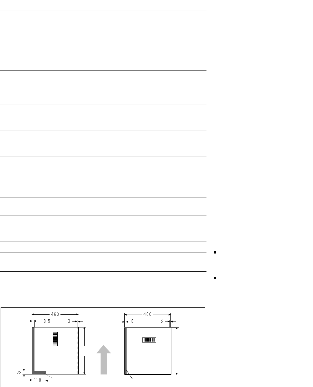
Bar-code-free PCB edge 3 mm on left and right parallel to PCB
transport direction (the additional restric-
tions shown in figure at the bottom apply
for scanning the bar code from above)
Label dimensions
Stroke width: W: 0.19 < W ≤ 0.3 mm
(corresponds to high + medium density)
Stroke length: ≥ 4 mm*
Length of scanning window: ≤ 90 mm
Label alignment on PCB** Parallel or at right angles to the PCB
transport direction, preferably next to
fixed conveyor side
Recommended label colors
(contrast ratio > 70%
as per DIN 66236)
Color coding: black, dark green or dark blue
Background: white, beige, yellow, orange
Code types Code 39, Code 128 / EAN 128,
Codabar, 2/5 IATA 2/5 industrial,
2/5 interleaved, UPC, EAN,
Pharma Code, EAN Addendum
(more upon request)
Complete bar code Max. 25 characters
Definition of a bar code filter possible
Safety of the laser scanner Laser diode 670 nm (red) / 1 mW
Laser protection class 2, degree of protec-
tion IP65
Station and line software from Version 401.xxx
Scan-in/analysis time
Slack time (T ≤ 1 s), as parallel to the
placement of preceding PCB
* This value can only be met if the bar code label on the PCB moves through the bar code scanner at
right angles to the machine’s direction of transport.
** Depending on where the bar code label is located on the PCB, the position of the bar code scanner
can be easily adjusted in the input conveyor belt.
restricted
460
restricted
11
Description
SIPLACE S-23 HM is equipped
with two component changeover
tables to the left and right of the
PCB conveyor. The total capacity
is, e.g. 2 x 40 tape tracks, each
8 mm wide.
The component feeders are sta-
tionary during the placement proc-
ess, therefore it is possible to re-
plenish the components (e.g., in
sticks) or to splice on tapes with-
out machine idle.
For the changeover, individual
feeders or all the changeover ta-
bles can be exchanged without any
tools for component tables which
have been set up in advance out-
side the placement machine.
Using component bar codes with
the aid of an optional component
bar code scanner guarantees the
correct allocation of the compo-
nent to the track.
To fully utilize the advantages of
the component changeover tables,
the entire set-up include checks
can also be conducted outside the
machine at the optional SIPLACE
set-up station. The changeover ta-
bles are equipped with rollers and
have an integrated pneumatic lift-
ing device, avoiding the use of a
lifting cart as with the SIPLACE 80
modules. Exchanging the tables
takes less than 2 minutes per
module.
Component Supply:
Changeover Table
Technical Data
Insert (exchangeable) In all SIPLACE placement modules
Feeder locations 20 x 8 mm dual track per table =
40 x 8 mm tracks, 2 tables per machine
Feeder modules SIPLACE feeder
for tapes, stick magazines, Bulk Cases
Accessories Tape container, waste container,
lift cart, empty tape cutter
Splicing Tool
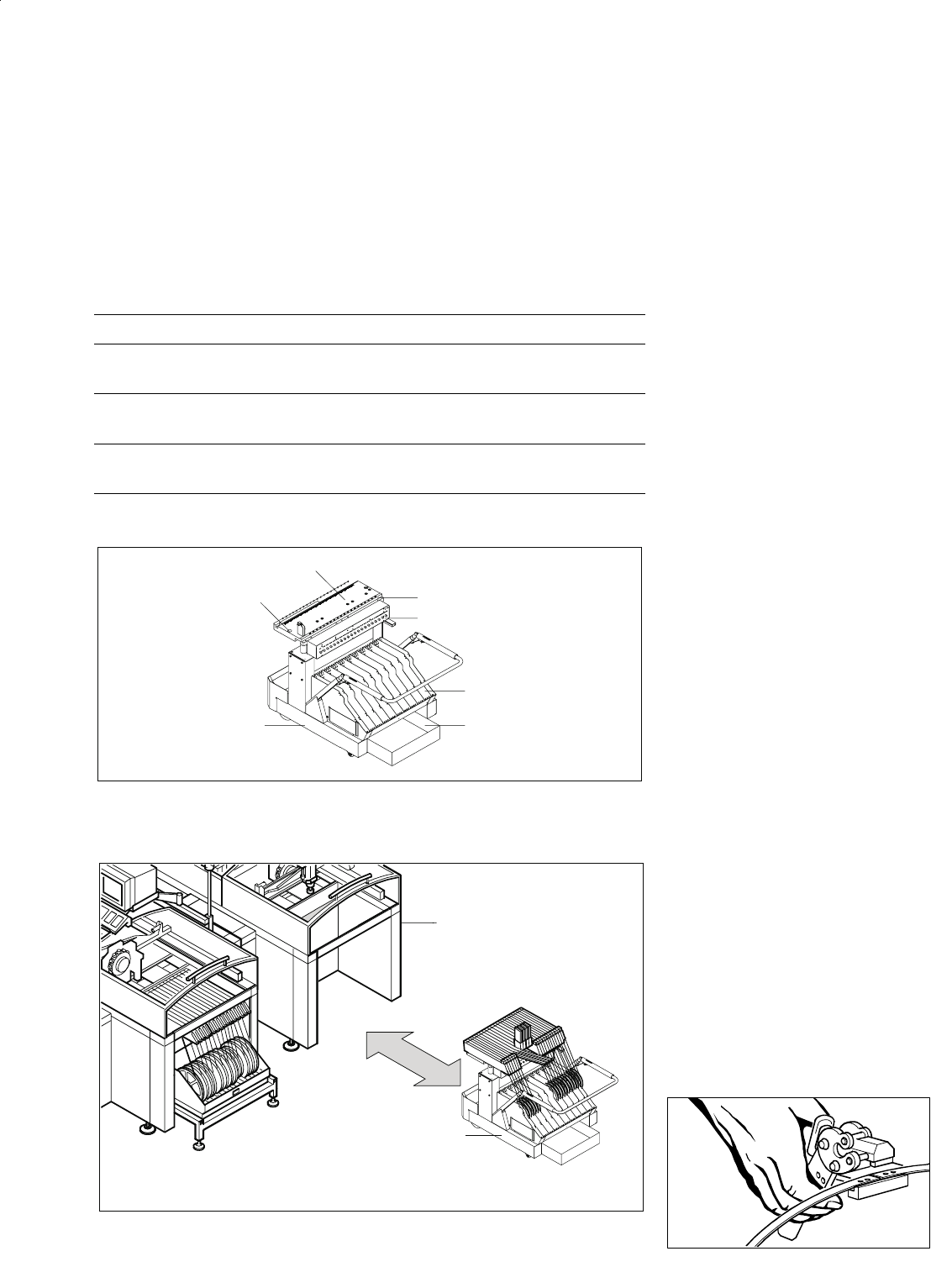
Exchange of a Feeder Changeover Table
Construction of a Changeover Table
Mobile
Changeover
Table
Feeder Table
Centering Position
SIPLACE Station
Compressed Air
Feeder Connection
Reel Container
Reject Bin
Mobile
Changeover
Table