Specification_SIPLACE_S23HM_eng.pdf - 第17页
16 Description When a batch change occurs, the changeover tables can be set up and checked at the external SIPLACE se t-up st ation quickly and without machine idle time. The costs for prod uction of a vast number of var…
15
Description
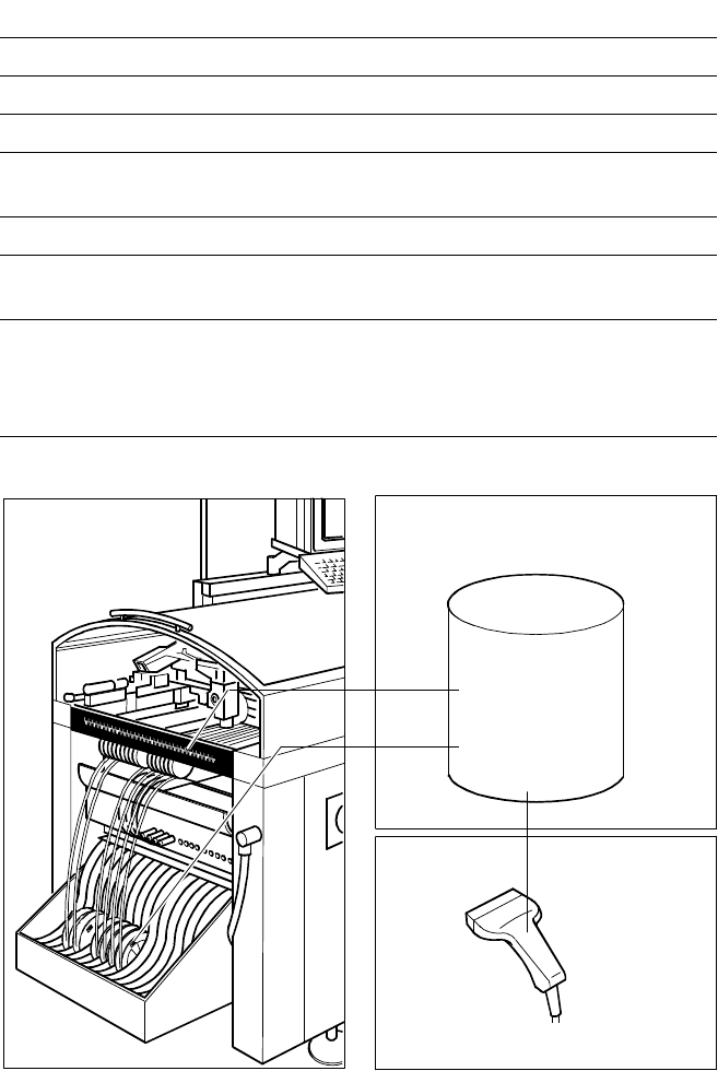
The component bar code scanner
enables a speedy, reliable set-up
and refill check. To this end the bar
codes of the tracks (on the track
scale on the feeder table) and the
components allocated to them (bar
code labels on tapes, Bulk Cases,
etc.) are read in with a hand scan-
ner. An audible and optical signal
acknowledges a successful read-
ing operation. If a label is dam-
aged, the bar code can also be en-
tered at the keyboard.
The allocation of the components
to their respective track is de-
scribed in the set-up data. If the
data received from the bar code
scanner does not correspond with
the set-up data, an error message
is displayed.
If the set-up check is switched on,
it becomes a mandatory step in
the set-up process. If it is switched
off, the set-up check is optional.
Component Supply:
Component Bar Code Scanner for Set-Up and Refill Check
(Option)
Component
Control
Set-Up File
Track Bar Code
Scanner
Technical Data
Connection Station computer
Data entry Bar code scanner or keyboard
Number of characters max. 40
Restrictions Bar codes beginning with number 1 or 2
or with less than 5 characters
Number of bar codes max. 6 per component
Number of filters to blank out
data max. 1 per bar code
Preset types of codes Code 39 (standard or full ASCII),
Code 2 from 5 interleaved and normal,
Code 128, UPC/EAN/JAN codes
(more upon request)
The scanner checks the corresponding track and the components.
Component
Bar Code
16
Description
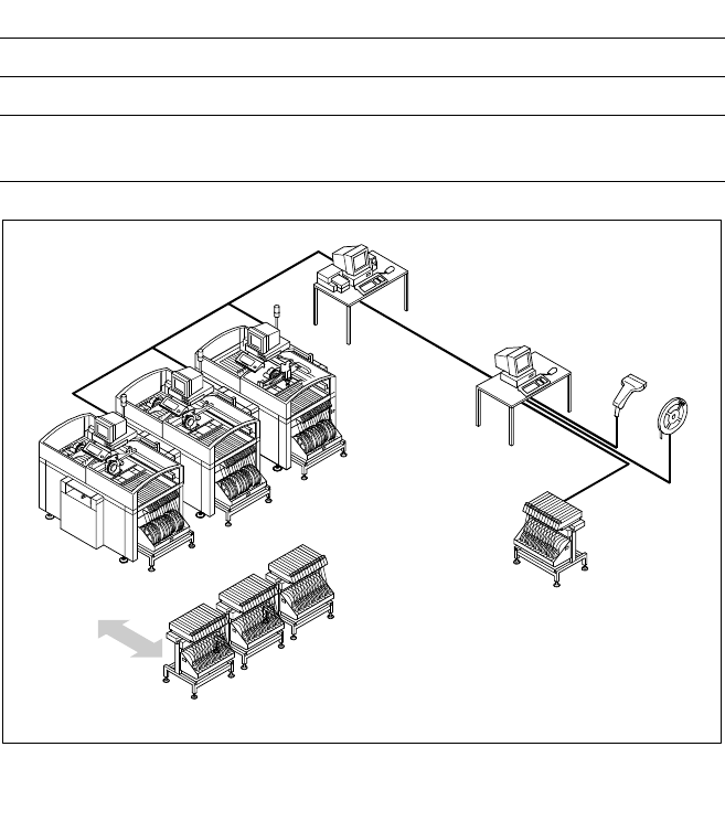
When a batch change occurs, the
changeover tables can be set up
and checked at the external
SIPLACE set-up station quickly and
without machine idle time. The
costs for production of a vast
number of variants are greatly re-
duced. When a bar code check is
conducted outside the machine,
10 minutes of machine idle time
are eliminated per set-up change.
Access to all current set-up data
from as many as 4 lines exists via
a link to a Local Area Network
(LAN) for the line computer.
Two component changeover ta-
bles belong to the standard
equipment of an SIPLACE
S-23 HM. Additional component
changeover tables are required for
optimal use of the set-up station.
Component Supply:
External SIPLACE Set-Up Station (Option)
Example for SIPLACE Set-Up Station
PC for External
Set-Up
LAN Scanner
Serial Interface
Line Computer
Line
LAN
Accessories
Operating system Windows NT 4.0
Set-up check Using bar code scanner
Time required:
Component table change 2 min / table side
Tape Reel
with
Bar Code
Changeover
Table
Component Changeover Tables
17
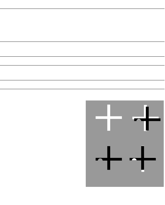
Target Low
Structure Correlation
Description
With the SIPLACE S-23 HM, sev-
eral vision modules with a central
vision system to analyze recorded
image data ensure high placement
precision.
At one of the machine’s two X-
gantries the PCB vision module
recognizes offsets in the position
of the PCB in the conveyor sys-
tem. The modules are also re-
quired to scan the machine or the
feeders on one side of the table.
Each vision module consists of a
CCD camera with integrated light-
ing and optics.
The offsets in PCB position are de-
termined with the help of at least
two - but generally three - refer-
ence marks on the PCB. When the
PCB arrives, the gantry with its
PCB vision module moves to the
programmed mark position. The
vision system compares the re-
corded video image with the sam-
ple stored in the PCB description.
By applying the correlation princi-
ple the vision system can deter-
mine the correct position through
comparisons with programmed
target structures even when refer-
ence marks are incomplete or
damaged (actual structures).
The shapes are not inviolably
specified; they can be taught with-
out restrictions.
Additional functions of the PCB vi-
sion module are the position rec-
ognition of the feeders and ce-
ramic substrates (optional) and the
calculation of processing data in-
cluding mapping.
In addition, recognition of faulty
PCBs is conducted via ”ink spots”
with the aid of the PCB vision
module.
Vision Sensor Technology:
PCB Vision Module
Technical Data
Reference marks
Local marks
Library memory
Recognition of poor panels
up to 3 (subpanels and multiple panels)
up to 2 per component
(may be of different type)
up to 255 types of reference marks
per subpanel
Image analysis Correlation principle
based on gray-scale values
Lighting method Front lighting
Recognition time
mark/ink spot
0.8 s
Camera’s field of view 5.7 x 5.7 mm
Correlation Principle
Actual High
Structure Correlation