Specification_SIPLACE_S23HM_eng.pdf - 第24页
23 12-Nozzle Revolver Head X-/Y- Portal System Fixed Component Supply Fixed PCB Description P P P Pl ll lac ac ac ace e e em m m me n en en ent t t t R R R Re e e el i li li lia a a ab b b b ili ili ili ilit t t ty y y y…
22
Description
Various factors contribute to the
placement precision of the
SIPLACE S-23 HM system, for ex-
ample the PCB which is stationary
during the placement process.
Components previously placed are
not affected by any forces of ac-
celeration, therefore their position
remains stable. The PCB is moved
in and out at a coordinated speed
which is automatically reduced just
before reaching the target position.
A further guarantee of long-term
high placement precision is the
position recognition feature of the
gantry and placement axes by op-
tical scanning of increment encod-
ers. Revolving star and segments
of the revolver head are positioned
by means of high-resolution glass
incremental panels. The X- and Y-
axes are positioned with the aid of
metal scales on each gantry axis.
In order to ascertain the placement
precision on SIPLACE machines,
high-precision glass components
with applicated structures are
placed on a dimensionally accurate
glass mapping calibration board.
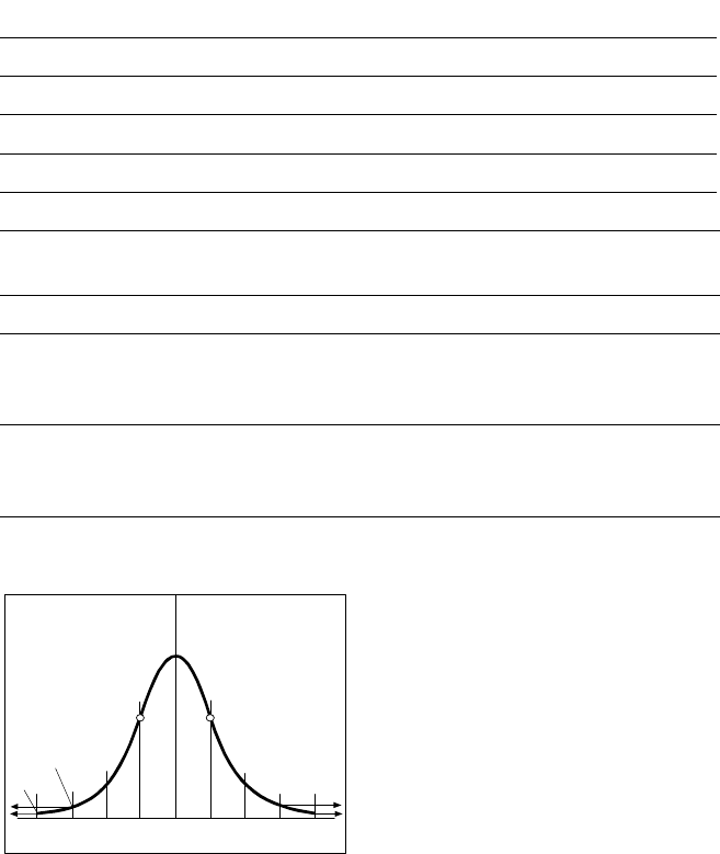
The results are analyzed statisti-
cally and represented as a Gaus-
sian standard distribution. In the
case of the 12-nozzle revolver
head the placement precision is
± 90 µm at a statistical reliability of
4 sigma. In other words, out of one
million placed components 60 may
be outside the specified tolerance
(- 60 dpm). If the accuracy value
± 90 µm is divided by the sigma
value 4, the result is the standard
deviation S of 1 sigma =
± 22.5 µm.
A machine capability analysis is
conducted for each machine ac-
ceptance test.
Machine Criteria:
Placement Accuracy
2700 dpm
60 dpm
Standard Deviation - dpm
P Point of Inflection
Technical Data Gantry
Drive AC servomotors
Position measuring system (X/Y) Linear scales
Resolution of X-/Y-axis
2.5 µm
Speed of X-axis max. 2.5 m/s
Speed of Y-axis max. 2.5 m/s
Accuracy
X-/Y- and D-axis offset in optical component and PCB centering
Angle accuracy ± 0.525° / 3 σ
± 0.70° / 4 σ
± 1.05° / 6 σ
Placement accuracy
± 67.5 µm/ 3 σ
± 90 µm/ 4 σ
± 135 µm/ 6 σ
-4
σ
-3
σ
-2
σσ
x
σ
2
σ
3
σ
4
σ
23
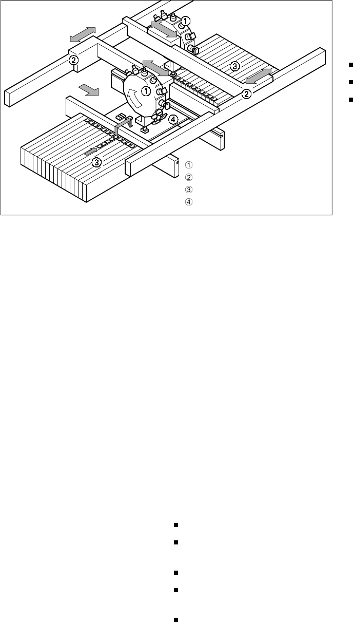
12-Nozzle Revolver Head
X-/Y- Portal System
Fixed Component Supply
Fixed PCB
Description
P
PP
Pl
ll
lac
acac
ace
ee
em
mm
men
enen
ent
t t
t R
RR
Re
ee
eli
lili
lia
aa
ab
bb
bili
iliili
ilit
tt
ty
yy
y
Aside from correct positioning,
placement reliability also signifies
gentle handling of the components
so that they can also be soldered
well later. This minimizes or elimi-
nates rework.
This is guaranteed on the SIPLACE
S-23 HM, for example, by a num-
ber of check functions such as the
vacuum checks and the compo-
nent vision test during the revolver
head cycle. Unsuitable compo-
nents are rejected, placed on a re-
pair list and automatically added
during a repair cycle. An offset in
the position of the PCB relative to
the conveyor system (PCB vision
module) and an X-, Y- or rotational
offset of the component relative to
the midpoint of the nozzle (com-
ponent vision module) result in
immediate correction and thus
placement precision.
Thanks to the stationary PCB the
components remain in their exact
placement position. The stationary
component table protect, for ex-
ample, the components in Bulk
Cases from damage such as may
occur due to vibrations which are
unavoidable with other placement
concepts. Optional add-on prod-
ucts provide further reliability. The
component bar code scanner de-
pendably recognizes components
which were set up incorrectly. The
correct placement program is
automatically sent to the station by
using the PCB bar code
P
PP
Pi
ii
ic
cc
ck
kk
k-
--
-u
uu
up
p p
p e
ee
err
rrrr
rro
oo
or
rr
rs
ss
s
All errors which occur between the
time the component is picked up
and the time it is placed on the
PCB are pick-up errors. They in-
clude:
No component in the tape
Component cannot be removed
from the tape.
Vacuum error
Vision error due to faulty com-
ponent
Vision error due to unrecognized
component
P
PP
Pl
ll
la
aa
ac
cc
ce
ee
em
mm
me
ee
en
nn
nt
t t
t e
ee
err
rrrr
rro
oo
or
rr
rs
ss
s
Errors which occur after the com-
ponent has been placed on the
PCB. They include:
Rotation error
Too many components on PCB
X/Y-offset
P
PP
Pl
ll
la
aa
ac
cc
ce
ee
em
mm
me
ee
en
nn
nt
t t
t S
SS
Sp
pp
pee
eeee
eed
dd
d
SIPLACE S-23 HM achieves a
maximum placement speed of
23,000 components per hour (cph).
This benchmark rate can be veri-
fied with a demonstration PCB at
Siemens.
The SIPLACE concept is based on
a horizontal axis of rotation of the
12-nozzle revolver head, the sta-
tionary component table and the
PCB which is motionless during
placement. This principle permits
a revolving start cycle time of
140 ms regardless of the compo-
nent. For this reason, the bench-
mark rate is already close to the
placement speed in actual practice.
Nevertheless, various factors exert
a certain influence, e.g. the PCB
size, the number of components
per PCB and their layout. The
SIPLACE concept also has a posi-
tive effect here, too, because, un-
like other concepts, it permits a
further optimization of positioning
and sequence.
The placement speed in actual
practice can be predicted on the
basis of a computation program.
Machine Criteria:
Placement Reliability and Placement Speed
Placement Principle SIPLACE S-23 HM
24
Corrected
Position
Description
Slight distortions of the gantry axis
cannot always be avoided despite
the highly stable machine frame.
With the aid of the mapping ap-
proach, the high placement preci-
sion of the machine is maintained
throughout its service life.
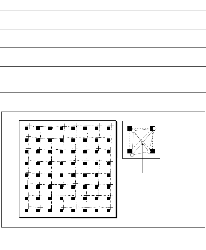
With this calibrating procedure,
which can be conducted quickly
and easily, the PCB camera recog-
nizes the fiducials on a mapping
calibration plate placed in its oper-
ating area. This board has highly
accurate marks on it. Any distor-
tions are located by comparing the
nominal grid on the mapping board
with the actual grid ”drawn” by
the placement head. These distor-
tions are taken into account during
all further positioning of the X-/Y-
axis and they are thus compen-
sated for.
Machine Criteria:
Mapping (Option)
Nominal Grid of Mapping Plate and Actual Grid with
Deviations Due to Gantry
Technical Data
Dimensions of the
mapping test board
520 x 460 mm (for single conveyor)
520 x 215 mm (for dual conveyor)
Number of measuring
points
13 x 11 (standard resolution)
26 x 21 (high resolution)
Ambient temperature
during calibration
+ 20° ± 3°C
Components of the
option
Test board (special glass)
Calculation data (diskette)
Case for safe storage