Specification_SIPLACE_S23HM_eng.pdf - 第26页
25 Description The control software coordinated with the modular a rchitecture of the SIPLACE placement line. It is based on a high-level realtime mul- titaski ng operating system which is optimally suited for controllin…
24
Corrected
Position
Description
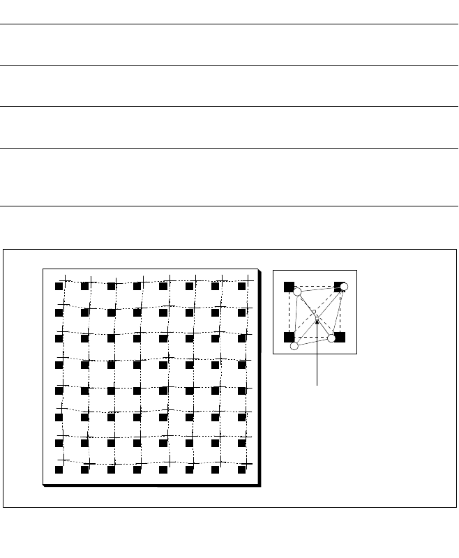
Slight distortions of the gantry axis
cannot always be avoided despite
the highly stable machine frame.
With the aid of the mapping ap-
proach, the high placement preci-
sion of the machine is maintained
throughout its service life.
With this calibrating procedure,
which can be conducted quickly
and easily, the PCB camera recog-
nizes the fiducials on a mapping
calibration plate placed in its oper-
ating area. This board has highly
accurate marks on it. Any distor-
tions are located by comparing the
nominal grid on the mapping board
with the actual grid ”drawn” by
the placement head. These distor-
tions are taken into account during
all further positioning of the X-/Y-
axis and they are thus compen-
sated for.
Machine Criteria:
Mapping (Option)
Nominal Grid of Mapping Plate and Actual Grid with
Deviations Due to Gantry
Technical Data
Dimensions of the
mapping test board
520 x 460 mm (for single conveyor)
520 x 215 mm (for dual conveyor)
Number of measuring
points
13 x 11 (standard resolution)
26 x 21 (high resolution)
Ambient temperature
during calibration
+ 20° ± 3°C
Components of the
option
Test board (special glass)
Calculation data (diskette)
Case for safe storage
25
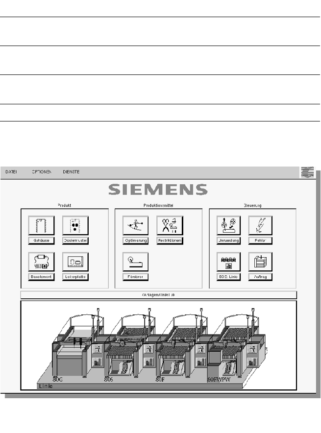
Description
The control software coordinated
with the modular architecture of
the SIPLACE placement line. It is
based on a high-level realtime mul-
titasking operating system which
is optimally suited for controlling
time-critical processes in the
placement machine. Window
technique and Touch-Screen inter-
face simplify the operation of line
and station computers which co-
operate closely in dividing the
tasks to be performed. The con-
text-sensitive on-line information
and help system comments, for
example, on current events in text
and graphics and offers short in-
formation for buttons in the toolbar
or in menu entries.
The UNIX Multitasking operating
system of the line computer
makes it possible to perform sev-
eral work sequences simultane-
ously. While PCB population is in
progress, it is already possible for
example to determine the opti-
mized layout of the feeders for the
next PCB type (set-up optimiza-
tion). It is also possible, without in-
fluencing the placement speed, to
edit in several windows and to
view the PDA/MDA data. When
production planning is physically
and organizationally separate from
the production facilities, it is advis-
able to utilize a second line com-
puter as an off-line programming
system.
SIPLACE Software Architecture:
System Architecture
Technical Data
Operating System:
Line computer SCO UNIX®
Station
computer
Microsoft® Windows with Touch-Screen
Machine controller RMOS®
(Realtime Multitasking Operating System)
Support On-line information and help system
Graphic Operator Environment

26
Description
The UNIX line computer is as-
signed the following interstation
tasks: Creation, revision and man-
agement of placement programs,
job data and component and GF li-
braries; automatic, optimized gen-
eration and management of ma-
chine equipment (set-up
optimization, set-up editors); de-
termination of optimized travel
paths for gantries and nozzle allo-
cations for the revolver heads:
control and supply of data to the
SIPLACE machines in a line; scan-
ning, storage and display of ma-
chine and production data; data
back-up on built-in magnetic tape
drive.
The Windows station computer
performs the following tasks in
conjunction with the machine con-
troller which has realtime capabil-
ity: Digital control of the machine
gantry systems; control of PCB
loading and unloading as well as
PCB conveyor; monitoring func-
tions, handling of disruptions and
output of error messages (includ-
ing help system); ensuring optimal
quality of the placement process;
optional set-up check by means of
component bar code and optional
placement program change by
means of PCB bar code.
SIPLACE Software Architecture:
Line Computer / Station Computer
Line Computer
Functions
Of the line computer Programming
Optimization
Control of the line machines
Monitoring the line machines
Data management by
Data manager
Of the station computer Machine control
Machine monitoring
Machine operation
Station Computer