Specification_SIPLACE_S23HM_eng.pdf - 第6页
5 Revolver Head Functions Component Pick-Up/ Placement Segment Removal Point Turning to the Placement Position Component Vision Description The 12-nozzle revolver head oper- ates on the Collect & Place princi- ple. I…
4
H
HH
He
ee
ea
aa
ad
d d
d m
mm
mo
oo
od
dd
du
uu
ul
ll
la
aa
ar
rr
ri
ii
it
tt
ty
yy
y
In the future it will be possible to
configure placement heads flexibly
to adapt the production line more
exactly to your requirement profile.
All SIPLACE S-23 HM machines
have been prepared for this modi-
fication.
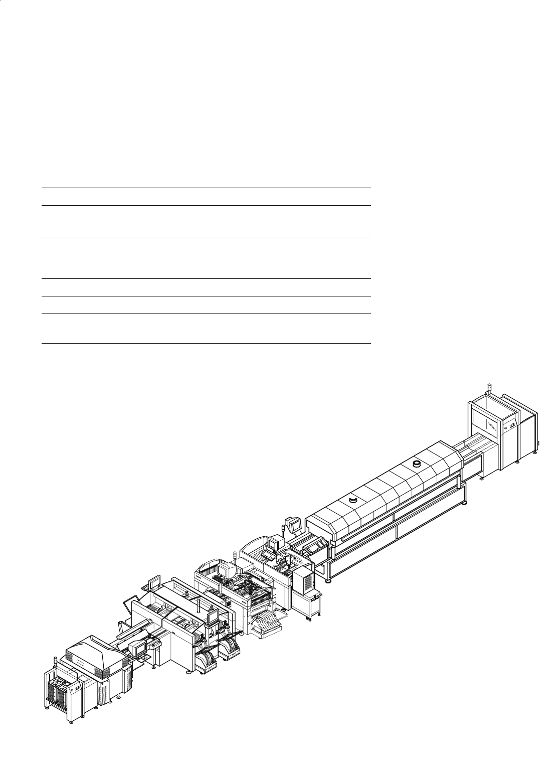
Input Station
Screen Printer
Oven
SIPLACE S-23 HM
SIPLACE HS-50
SIPLACE 80 F
5
with Waffle Pack Changer
Output
Station
Example of a SIPLACE Placement Line
Description
M
MM
Ma
aa
ac
cc
cr
rr
ro
oo
om
mm
mo
oo
od
dd
du
uu
ul
ll
la
aa
ar
rr
ri
ii
it
tt
ty
yy
y
Flexibility and adaptability are the
outstanding characteristics of the
modular SIPLACE concept. It en-
ables a production line with an in-
dividual combination of identical
and different types of modules.
When the performance require-
ments change, the individual ma-
chines ca be recombined quickly
and easily, because of their rela-
tively small size for example.
The SIPLACE family offers the
right product for each purpose -
from the super high-speed place-
ment system SIPLACE HS-50 to
the high-speed SMD placement
system SIPLACE S-23 HM and the
flexible Fine Pitch placement sys-
tem SIPLACE F
5
.
Line Design
Technical Data
System SIPLACE SMD placement lines
Modules SIPLACE HS-50 / SIPLACE S-23 HM /
SIPLACE F
5
Peripherals Input/output station, screen printer,
solder oven, inspection conveyor etc.,
available from Siemens
Component range 0201* to 55 x 55 mm**
Placement speed depends on layout of modules
Space required 4 m² / SIPLACE S & F modules
7.5 m² / SIPLACE HS module
* Collect & Place
** Pick & Place
5
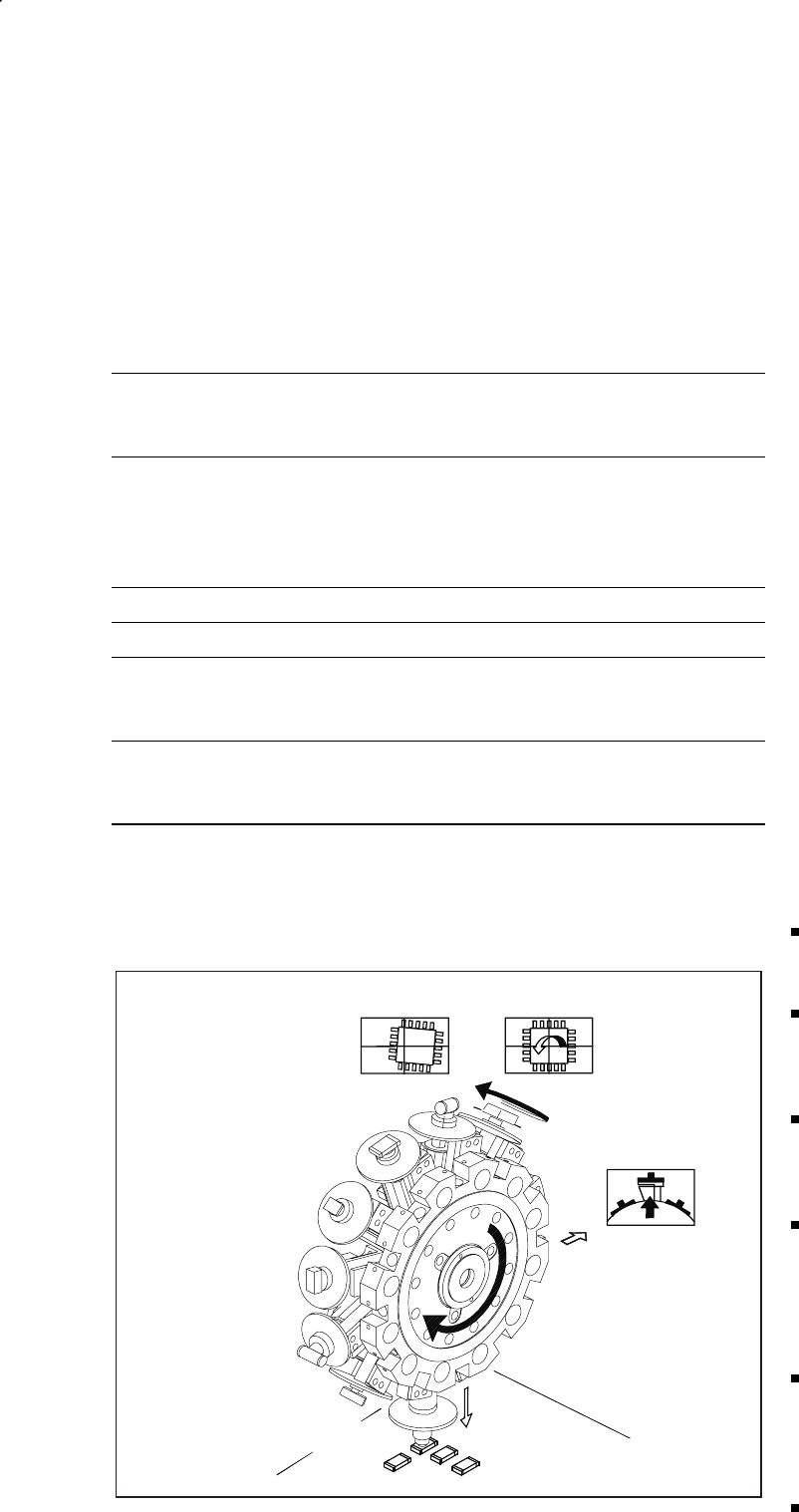
Revolver Head Functions
Component Pick-Up/
Placement
Segment
Removal
Point
Turning to
the Placement
Position
Component
Vision
Description
The 12-nozzle revolver head oper-
ates on the Collect & Place princi-
ple. In contrast to classic shooters,
the 12 vacuum nozzles of the
SIPLACE revolver heads rotate
around a horizontal axis. This does
not just save space: Due to the
small diameter compared to
shooters, the centrifugal forces
which develop are significantly
lower. The results are high-speed,
reliable placement and the same
cycle time for all components.
Components are picked up and
placed gently and reliably with the
aid of vacuum or blast air. A num-
ber of vacuum tests indicate
whether the component has been
picked up and placed accurately.
Various control and self-learning
functions further enhance the de-
pendability of the system:
The optical recognition of feeder
positions furnishes the exact
position of the feeder table.
A camera on the revolver head
(component vision module) de-
termines the exact position of
each component on the nozzle.
Offsets in position are corrected
prior to placement and taken
into consideration during further
component pick-up.
In addition, the package form is
also checked. If the actual geo-
metric dimensions of the com-
ponent do not correspond to
those programmed, the place-
ment is not carried out.
Irregularities in the PCB surface
are balanced out due to the
sensor-stop operation while the
nozzle is being lowered and they
are also ”learned”.
Components recognized as be-
ing faulty are rejected by blast
air and are automatically added
during a repair run.
Placement Heads:
12-Nozzle Revolver Head for High Speed
Technical Data
Component spectrum* 0402 (0201**) to 18.7 x 18.7 mm,
incl. BGA, µBGA, Flip Chip, QFP,
TSOP, PLCC, SO to SO32, DRAM
Max. height*
min. lead pitch
min. dimensions
max. dimensions*
max. weight*
6 mm
0.5 mm
0.5 x 1.0 mm
18.7 x 18.7 mm
2 g
Stroke of Z-axis max. 16 mm
Programmable placement force 2.4 to 5.0 N
Angle accuracy
± 0.525° / 3 σ
± 0.70° / 4 σ
± 1.05° / 6 σ
Placement accuracy
± 67.5 µm/ 3 σ
± 90 µm/ 4 σ
± 135 µm/ 6 σ
* A uniformly reliable, speedy and accurate placement is guaranteed up to these limit values. Above
and beyond this, components can be placed if they satisfy specific basic conditions (For other
components please contact Siemens).
** 12-nozzle revolver head is capable of handling 0201 (Please contact Siemens).
6
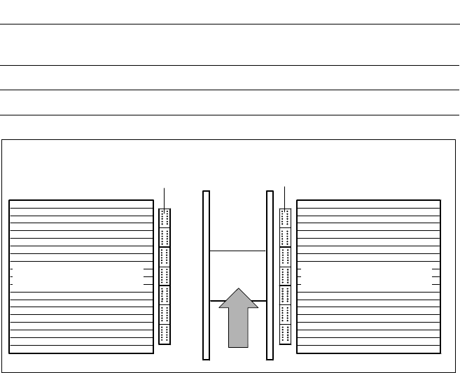
Description
One nozzle changer can be in-
stalled for the 12-nozzle revolver
head on each the left and right of
the PCB conveyor with no loss of
feeder locations. The revolver head
changes the placement quickly and
reliably for the nozzle configuration
required for a particular job. Dam-
aged or faulty nozzles can be ex-
changed via menu function.
Placement Heads:
Nozzle Changer for 12-Nozzle Revolver Head (Option)
Nozzle Changer for
12-Nozzle Revolver Head
for 7 Ma
g
azines for 12 Nozzles (O
p
tion)
Technical Data
Type of nozzle All standard nozzles of nozzle series 9xx
(special nozzles have to be checked individually)
Capacity 7 magazines for 12 nozzles
Nozzle changing times About 2 s per nozzles
Component Feeder
Component FeederPCB