Specification_SIPLACE_S23HM_eng.pdf - 第8页
7 PCB Transpor t Direction Description On SIPLAC E S-23 HM placement machines the in-line conveyor sys- tem ensures a speedy adjustment to new PCB widths. The changeo- ver is made either at the station via menu function …
6
Description
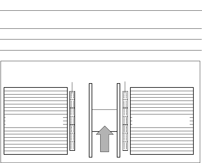
One nozzle changer can be in-
stalled for the 12-nozzle revolver
head on each the left and right of
the PCB conveyor with no loss of
feeder locations. The revolver head
changes the placement quickly and
reliably for the nozzle configuration
required for a particular job. Dam-
aged or faulty nozzles can be ex-
changed via menu function.
Placement Heads:
Nozzle Changer for 12-Nozzle Revolver Head (Option)
Nozzle Changer for
12-Nozzle Revolver Head
for 7 Ma
g
azines for 12 Nozzles (O
p
tion)
Technical Data
Type of nozzle All standard nozzles of nozzle series 9xx
(special nozzles have to be checked individually)
Capacity 7 magazines for 12 nozzles
Nozzle changing times About 2 s per nozzles
Component Feeder
Component FeederPCB
7
PCB Transport
Direction
Description
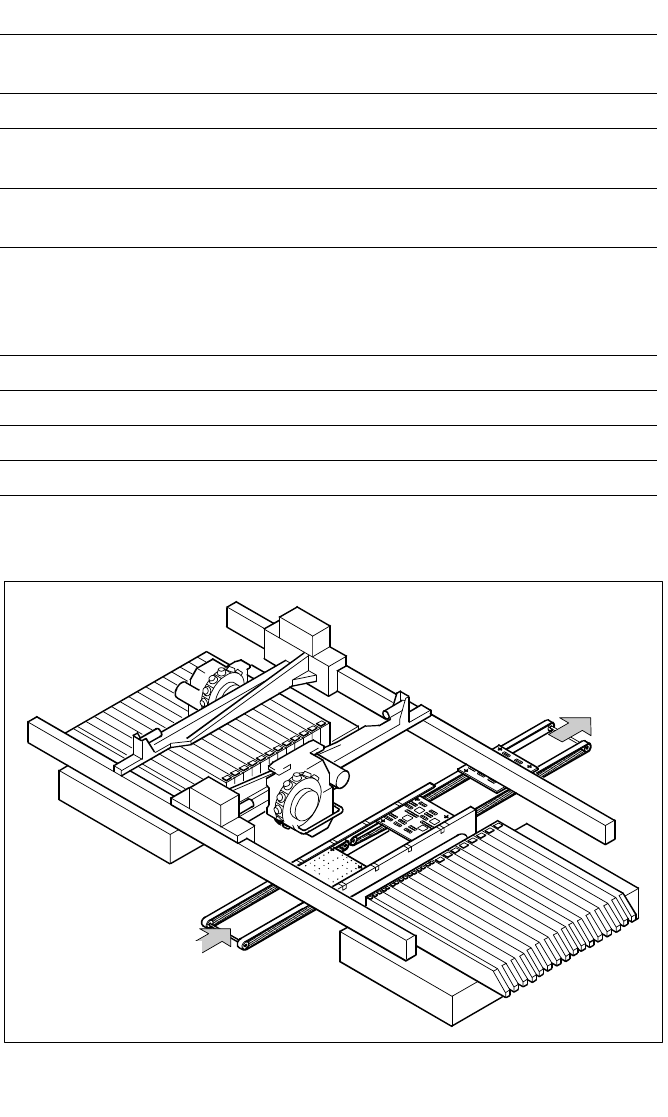
On SIPLACE S-23 HM placement
machines the in-line conveyor sys-
tem ensures a speedy adjustment
to new PCB widths. The changeo-
ver is made either at the station via
menu function or from the line
computer via the automatic width
adjustment. Ceramic substrates
are also transported or fixed in
place by means of the optional ce-
ramic substrate centering feature.
As standard the SIPLACE place-
ment system are available with a
single conveyor system.
PCB Conveyor:
Single Conveyor
PCB Conveyor
Technical Data
PCB dimensions 50 x 50 mm to 460 x 460 mm
(optional 460 x 508 mm)
PCB thickness 0.5 to 4.5 mm
Max. PCB warp Top: 4.5 mm - PCB thickness
Bottom: 0.5 mm + PCB thickness
PCB underside clearance Standard: 25 mm,
Option: max. 40 mm
PCB conveyor height
830 ± 15 mm (Standard)
900 ± 15 mm (Option)
930 ± 15 mm (Option)
950 ± 15 mm (Option) SMEMA
Fixed conveyor edge On right (standard); on left (option)
Type of interface Siemens (standard); SMEMA (option)
Component-free handling edge 3 mm
PCB changing time 2.5 s
8
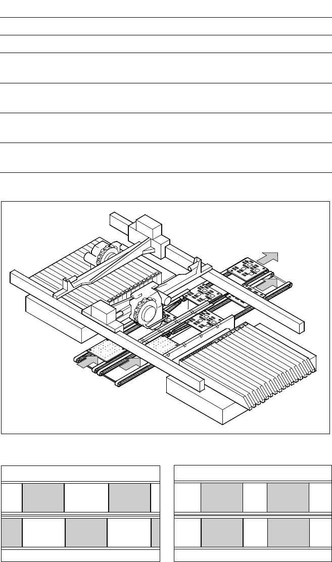
PCB Transport
Direction
Asynchronous
Synchronous
Description
Thanks to the reduced non-
productive times, the dual PCB
conveyor can effect a considerable
increase in the throughput, de-
pending on the program. It enables
the simultaneous (synchronous) or
alternating (asynchronous) trans-
port of two PCBs through the
placement machine.
In the case of the synchronous
type of transport it is possible, for
example, to process the top and
bottom of the PCB without using
the cluster technique.
In the case of the asynchronous
type of transport one PCB can be
moved into the placement ma-
chine during slack time while an-
other one of the same type is be-
ing populated. The portion of non-
productive time caused by the
transport of the PCB is therefore
completely eliminated. The in-
crease in placement speed to be
expected is between 10% and
30%, depending on component
load of the PCB.
Insofar as the customer is con-
cerned, switching between asyn-
chronous and synchronous dual
conveyor entails relatively little ex-
penditure. The optional ceramic
substrate centering is possible, the
PCB bar code mode is not.
PCB Conveyor:
Dual Conveyor
Asynchronous Dual PCB Conveyor
Technical Data
PCB dimensions 50 x 50 mm to 460 x 216.5 mm
Fixed conveyor edge On right (standard); on left (option)
Placement program per conveyor Synchronous: same or different
Asynchronous: same
PCB width per conveyor Synchronous: same or different
Asynchronous: same
Ink spot recognition Synchronous: not possible
Asynchronous: possible
Automatic width adjustment Synchronous: not possible
Asynchronous: possible