00194994_01.pdf - 第15页
SIPLACE Software Guide Version 408.xx 2 Introduction and basic terms Issue 03/06 EN 2.2 Overview 15 2 Fig. 2.2 - 4 Overview of the SIPLACE CF and F5 HM without WPC Key to Fig. 2.2 - 4 (1) Collect&Place placemen t hea…
2 Introduction and basic terms SIPLACE Software Guide Version 408.xx
2.2 Overview Issue 03/06 EN
14
2.2.2 Overview of the SIPLACE CF and F5 HM
2
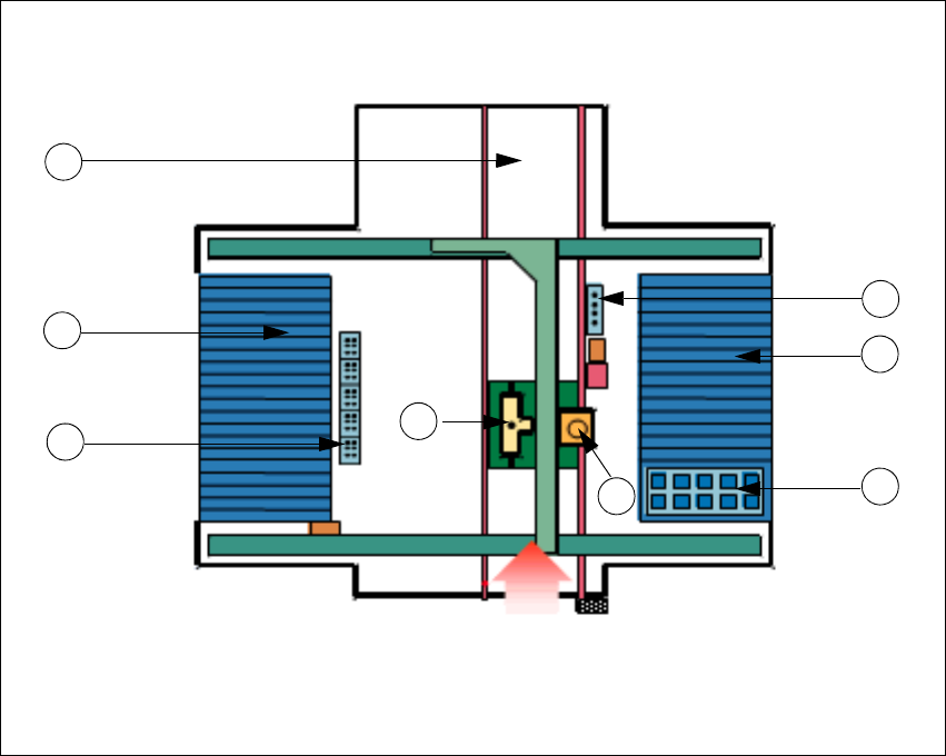
Fig. 2.2 - 3 Overview of the SIPLACE CF and F5 HM with WPC
Key to Fig. 2.2 - 3
(1) Collect&Place placement head on gantry 1
(2) Pick&Place placement head on gantry 1
(3) Nozzle changer for Collect&Place placement head
(4) Nozzle changer for Pick&Place placement head
(5) Location 1 (with WPC)
(6) Location 2 (with component table)
(7) Location 3 (with changeover table)
(8) PCB conveyor (dual conveyor for SIPLACE F5 HM)
Transport direction
5
2
8
3
7
4
1
6
SIPLACE Software Guide Version 408.xx 2 Introduction and basic terms
Issue 03/06 EN 2.2 Overview
15
2
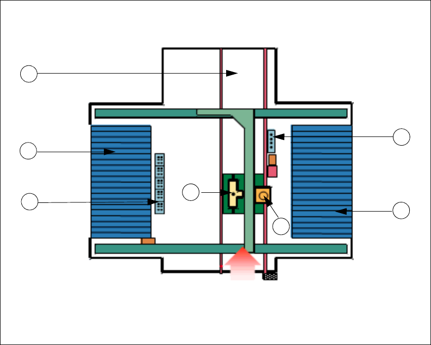
Fig. 2.2 - 4 Overview of the SIPLACE CF and F5 HM without WPC
Key to Fig. 2.2 - 4
(1) Collect&Place placement head on gantry 1
(2) Pick&Place placement head on gantry 1
(3) Nozzle changer for Collect&Place placement head
(4) Nozzle changer for Pick&Place placement head
(5) Location 1 (with changeover table)
(6) Location 3 (with changeover table)
(7) PCB conveyor (dual conveyor for SIPLACE F5 HM)
2
2
Transport direction
2
7
3
6
4
1
5
2 Introduction and basic terms SIPLACE Software Guide Version 408.xx
2.2 Overview Issue 03/06 EN
16
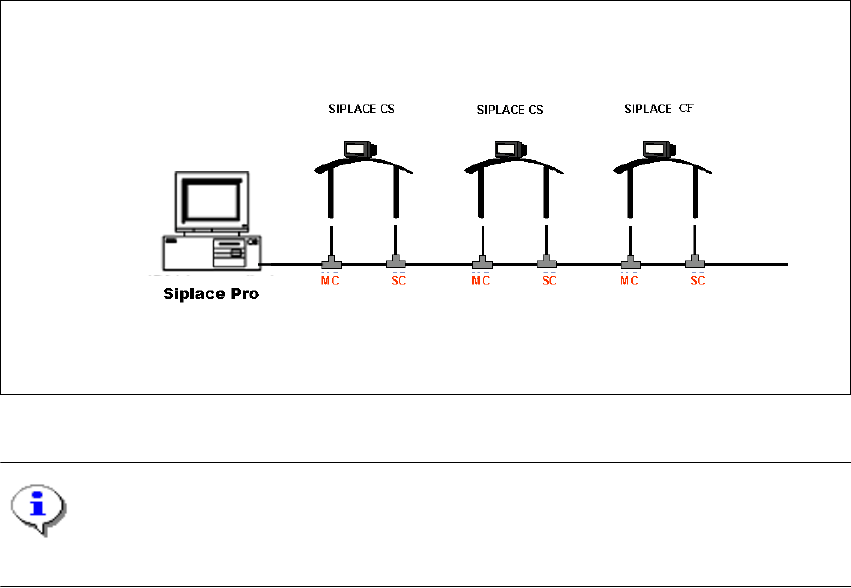
2.2.3 Overview of the system components that make up a SIPLACE line
2
The individual stations obtain their placement data from a control computer (SIPLACE Pro). 2
2
Fig. 2.2 - 5 Schematic diagram of the network in a SIPLACE line (example)
NOTE
A line with up to 5 stations is supported by the SIPLACE Pro programming system. 2
The placement data is sent by the job control facility on the host computer to the various stations.2
2