00194994_01.pdf - 第16页
2 Introduction and basic terms SIPLACE Software Guide Version 408.xx 2.2 Overview Issue 03/06 EN 16 2.2.3 Overview of the system com ponent s that make up a SIPLACE line 2 The individual stations obt ain their placement …
SIPLACE Software Guide Version 408.xx 2 Introduction and basic terms
Issue 03/06 EN 2.2 Overview
15
2
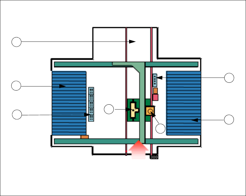
Fig. 2.2 - 4 Overview of the SIPLACE CF and F5 HM without WPC
Key to Fig. 2.2 - 4
(1) Collect&Place placement head on gantry 1
(2) Pick&Place placement head on gantry 1
(3) Nozzle changer for Collect&Place placement head
(4) Nozzle changer for Pick&Place placement head
(5) Location 1 (with changeover table)
(6) Location 3 (with changeover table)
(7) PCB conveyor (dual conveyor for SIPLACE F5 HM)
2
2
Transport direction
2
7
3
6
4
1
5
2 Introduction and basic terms SIPLACE Software Guide Version 408.xx
2.2 Overview Issue 03/06 EN
16
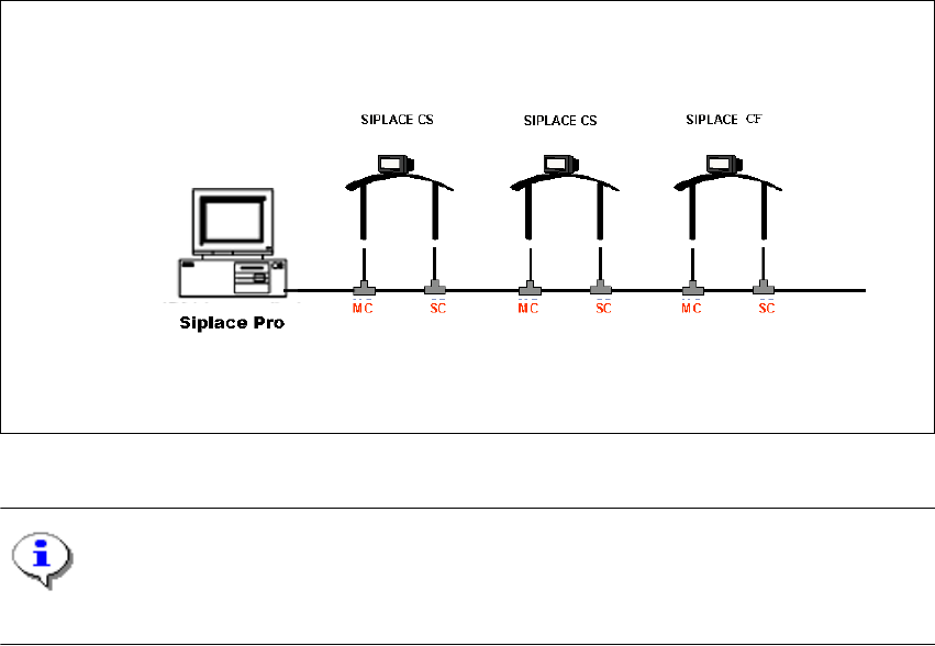
2.2.3 Overview of the system components that make up a SIPLACE line
2
The individual stations obtain their placement data from a control computer (SIPLACE Pro). 2
2
Fig. 2.2 - 5 Schematic diagram of the network in a SIPLACE line (example)
NOTE
A line with up to 5 stations is supported by the SIPLACE Pro programming system. 2
The placement data is sent by the job control facility on the host computer to the various stations.2
2
SIPLACE Software Guide Version 408.xx 3 Graphical user interface
Issue 03/06 EN 3.1 Inputs and controls
17
3 Graphical user interface
This section describes how to use the various controls such as the keyboard, trackball and mouse
buttons and also introduces the functions of the individual components of the graphical user inter-
face. 3
WARNING
In addition, the safety notes of the User Manual for the SIPLACE placement machines take
priority. 3
3.1 Inputs and controls
Keyboard 3
The keyboard with its integrated trackball and mouse buttons acts as the standard input tool for
the graphical user interface of the station computer software. 3
Touch screen 3
The touch screen acts as the input device for the SIPLACE machines S23 and F5 HM. 3
Trackball and mouse buttons 3
You use the trackball to move the mouse pointer across the user interface to the desired object
and then use the left mouse button to select the object or execute the appropriate function. 3
NOTE
In this guide, triggering an action using the left mouse button is always referred to as "clicking". 3
3