00194994_01.pdf - 第20页
3 Graphical user interface SIPLACE Software Guide Version 408.xx 3.2 Components of the user interface Issue 03/06 EN 20 3.2.1 Icons in the working or display area In main view , certain ope rating st atuses (processing ,…
SIPLACE Software Guide Version 408.xx 3 Graphical user interface
Issue 03/06 EN 3.2 Components of the user interface
19
Title bar 3
The title bar displays the name of the current view (e.g. Main view). 3
Menu bar 3
The menu bar contains menus, the contents of which (functions and options available in the menu)
may change depending on the current view. 3
Working area/display area 3
This area displays the controls (buttons, icons) used to set/trigger functions, along with the con-
tents of active menus and submenus, general messages, error messages and other comments.
In addition, in the Main view, animated and/or different color objects may be used to indicate cer-
tain processes or statuses (e.g. processing, feeder location empty etc.). 3
Controls 3
You trigger actions, select options or make settings by clicking the corresponding controls with the
left mouse button.
If a control is displayed in inverse video (light gray), this means that the conditions for the execu-
tion of the corresponding functions are not satisfied. 3
Toolbar 3
This bar contains buttons which are used to switch the user interface to a different view where you
can then perform the necessary operations. 3
Clicking a icon on the toolbar takes you to the view which corresponds to it. The icon matching the
active view then itself becomes inactive. 3
Status area 3
The status area displays the current machine status, the last error to have occurred and the action
which is to be performed by the operator. 3
Info bar 3
This bar displays concise information about the menu item or icon/button over which the mouse
pointer is currently positioned. The current control mode is displayed next to this in a separate
area. 3
3 Graphical user interface SIPLACE Software Guide Version 408.xx
3.2 Components of the user interface Issue 03/06 EN
20
3.2.1 Icons in the working or display area
In main view, certain operating statuses (processing, error etc.) are indicated by different icons or
by changes in the color of the corresponding graphic in the display area. 3
Meaning of the icons for the various different operating statuses 3
3
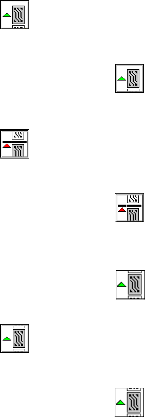
Processing PCB 3
This icon is active when the machine is ready to place or if processing was interrupted. 3
3
Æ Click the icon.
Processing is started.
3
Stop processing PCB 3
This icon is active during processing. 3
3
Æ Click the icon.
The machine is stopped as soon as the board in the intermediate conveyor has been comple-
tely assembled and moved into the output conveyor.
Then the
icon becomes active.
3
Continue processing 3
This icon is active after "Stop processing PCB" or after an error produces a machine standstill. 3
3
Æ Click the icon.
The board in the intermediate conveyor continues to be processed after the error has suc-
cessfully been eliminated.
SIPLACE Software Guide Version 408.xx 3 Graphical user interface
Issue 03/06 EN 3.2 Components of the user interface
21
3
Abort processing 3
This icon is active after an error occurs which leads to a machine standstill. 3
3
Æ Click the icon.
The current processing operation is aborted after you confirm the dialog box which appears.
The incompletely assembled PCB is transported to the output conveyor and the operator is re-
quested to remove it by hand.