00194994_01.pdf - 第24页
3 Graphical user interface SIPLACE Software Guide Version 408.xx 3.2 Components of the user interface Issue 03/06 EN 24 3.2.2 T oolbar in Main view 3 Fig. 3.2 - 2 T oolbar in the Main view (example: SIPLACE S23) Key to F…
SIPLACE Software Guide Version 408.xx 3 Graphical user interface
Issue 03/06 EN 3.2 Components of the user interface
23
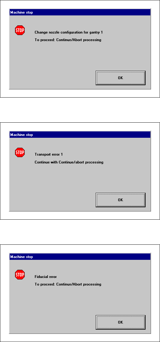
Nozzle configuration error 3
3
3
Transport error 3
3
3
Fiducial error 3
3
3
3
3
3
3
3
3
3

3 Graphical user interface SIPLACE Software Guide Version 408.xx
3.2 Components of the user interface Issue 03/06 EN
24
3.2.2 Toolbar in Main view
3
Fig. 3.2 - 2 Toolbar in the Main view (example: SIPLACE S23)
Key to Fig. 3.2 - 2
(1) Main view
(2) Set-up, placement functions
(3) Error, placement functions
(4) Component feeder, placement functions
(5) Gantry 1 and 2 (only SIPLACE CS and S23), single functions
(6) Conveyor or Dual conveyor (only S23 and F5 HM), single functions
(7) Teach fiducials, vision functions
(8) Test component, vision functions
(9) Start SITEST test program
3
Æ Click the required icon in the toolbar.
This switches the user interface to the appropriate view.
The icon corresponding to the view which is currently active itself becomes inactive.
3
1
2
3
4
5
6
7
8
9

SIPLACE Software Guide Version 408.xx 3 Graphical user interface
Issue 03/06 EN 3.3 User interface - views and menus
25
3.3 User interface - views and menus
3.3.1 Views
To perform a specific operation via the user interface, you may need to switch this to a different
view. You can do this by clicking the appropriate button on the toolbar (see section 3.2.2) or by
selecting the corresponding menu item from the "View" menu (see section 3.3.2.2). 3
3.3.2 Menus
3.3.2.1 "Mode" menu
The complete set of functions present in the "Mode" menu is only available in the main view.
In the views "Setup", "Errors" and "Feeders" and their sub-views, only the menu items "Stop pro-
cessing PCB" and "Processing PCB" are available. In the other views, the "Mode" menu is not
displayed. 3
NOTE
For a description of the menu items "Stop processing PCB", "Processing PCB" and "Continue pro-
cessing", refer to section 3.2.1. 3
Start OIS 3
This menu function starts the software for the "Operator Information System". The production data
acquisition system can be used to obtain information about the operating behavior of a complete
line or an individual station. 3
Configure SIPLACE Pro connection... 3
In this dialog box, you can specify which computer is permitted to provide the current station com-
puter with data: 3