00197674-01-UM-E-Series-EN-02-2015.pdf - 第138页
3 Technical data and assemblies User manual SIPLACE E 3.6 PCB conveyor system From software version SC 708.0 12/2014 E dition 138 3.6.4.2 PCB warpage during placement A warpage of 2 mm can lead to problems focussing on l…
User manual SIPLACE E 3 Technical data and assemblies
From software version SC 708.0 12/2014 Edition 3.6 PCB conveyor system
137
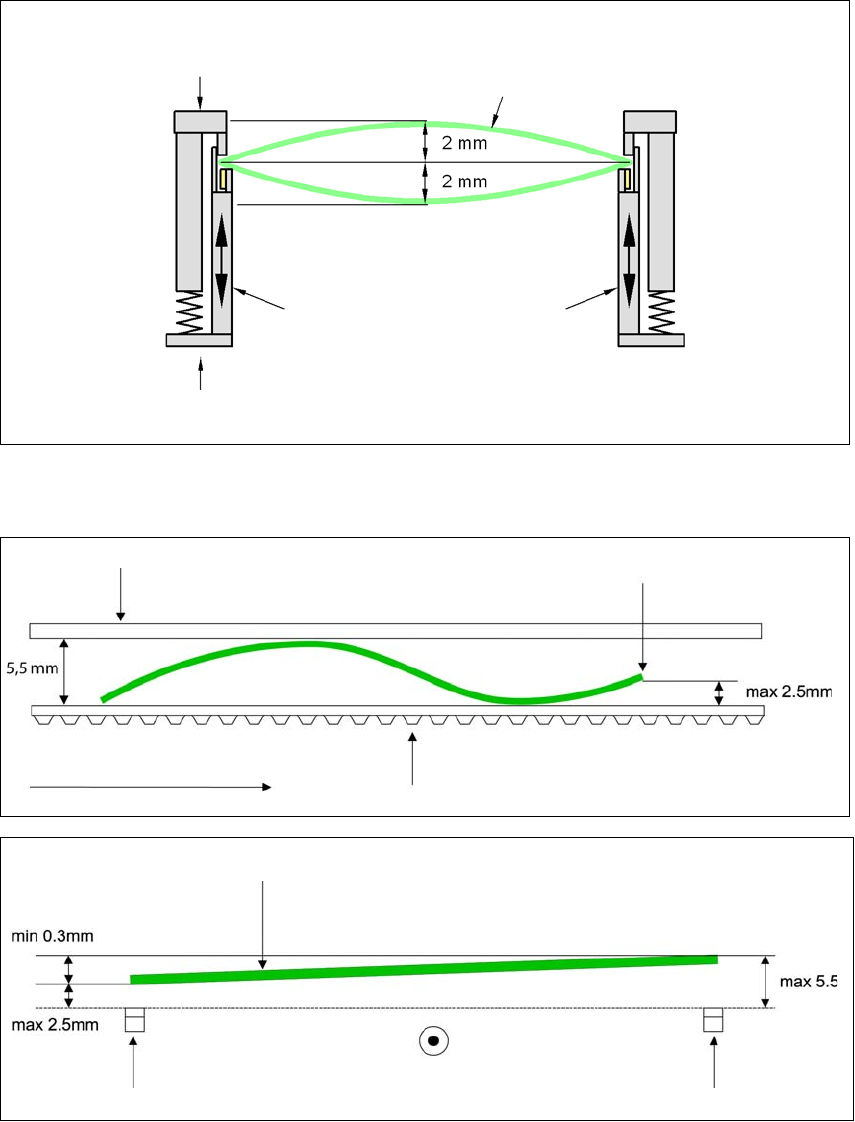
3.6.4 Definition of PCB warpage
3.6.4.1 PCB warpage on the conveyor
PCB warpage across the direction of travel max. 1% of the PCB diagonal, but not exceeding 2 mm
3
PCB warpage in the direction of transport + PCB thickness < 5.5 mm. Bending up of board edge
max. 2.5 mm.
3
3
Fixed clamped edge
Movable clamping device
Printed circuit board
Conveyor side wall
Fixed clamped edge
Conveyor belt
PCB transport direction
Front board edge
Front board edge
Left conveyor belt
Right conveyor belt
PCB transport direction
3 Technical data and assemblies User manual SIPLACE E
3.6 PCB conveyor system From software version SC 708.0 12/2014 Edition
138
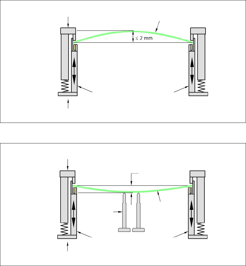
3.6.4.2 PCB warpage during placement
A warpage of 2 mm can lead to problems focussing on local fiducials and ink spots in the middle
of the PCB. The digital camera's focus is 2 mm. When all the tolerances are taken into account,
this value is reduced to 1.5 mm. Also note that the component height is reduced by the warpage.
3
3
PCB warpage down, max. 0.5 mm
3
Use magnetic pin supports to achieve this value.
Movable clamping device
Fixed clamped edge
Printed circuit board
Conveyor side wall
Printed circuit board
Magnetic pin
support
Movable clamping device
Fixed clamped edge
Conveyor side wall
0.5 mm
User manual SIPLACE E 3 Technical data and assemblies
From software version SC 708.0 12/2014 Edition 3.7 Vision system
139
3.7 Vision system
3.7.1 Structure
A component camera is integrated at each Collect&Place head (SIPLACE CP14/12/6). The com-
ponent camera, stationary, P&P type 33 GigE, type 36 GigE and type 25 GigE for the SIPLACE
TH/SIPLACE PP head is fixed to the machine frame.
The
component vision module
is used to determine:
– the precise position of the components at the nozzle and
– the geometry of the package form.
The
PCB vision module
uses fiducials on the PCBs to determine:
– the position of the PCB,
– its rotation angle
– and the PCB skew.
The PCB cameras are fixed to the bottom of the gantries. They use fiducials on the
feeder mod
-
ules
to determine the exact pick-up position of components, which is particularly important for
small components.