00197674-01-UM-E-Series-EN-02-2015.pdf - 第238页
5 Working with the machine User manual SIPLACE E 5.11 Setting up the feeder modules From software version SC 708.0 12/2014 Edition 238 5.11.4.4 Tape support for SIPLACE SmartFeeder 8 mm E module 5 Fig. 5.11 - 7 SIPLACE S…
User manual SIPLACE E 5 Working with the machine
From software version SC 708.0 12/2014 Edition 5.11 Setting up the feeder modules
237
Step3 5
5
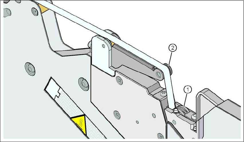
Fig. 5.11 - 6 Guiding the cover foil to the foil packing wheels
(1) Cover foil packing wheels
(2) Cover foil rocker
5
Guide the cover foil over the cover foil rocker (item 2) until it reaches the foil packing wheels
(item 1).
On the operator panel, press the FOIL button until the cover foil is tensioned. The cover foil
rocker points down and stops the drive motor.
Cut the component tape flush with the front end of the feeder module.
5 Working with the machine User manual SIPLACE E
5.11 Setting up the feeder modules From software version SC 708.0 12/2014 Edition
238
5.11.4.4 Tape support for SIPLACE SmartFeeder 8 mm E module
5
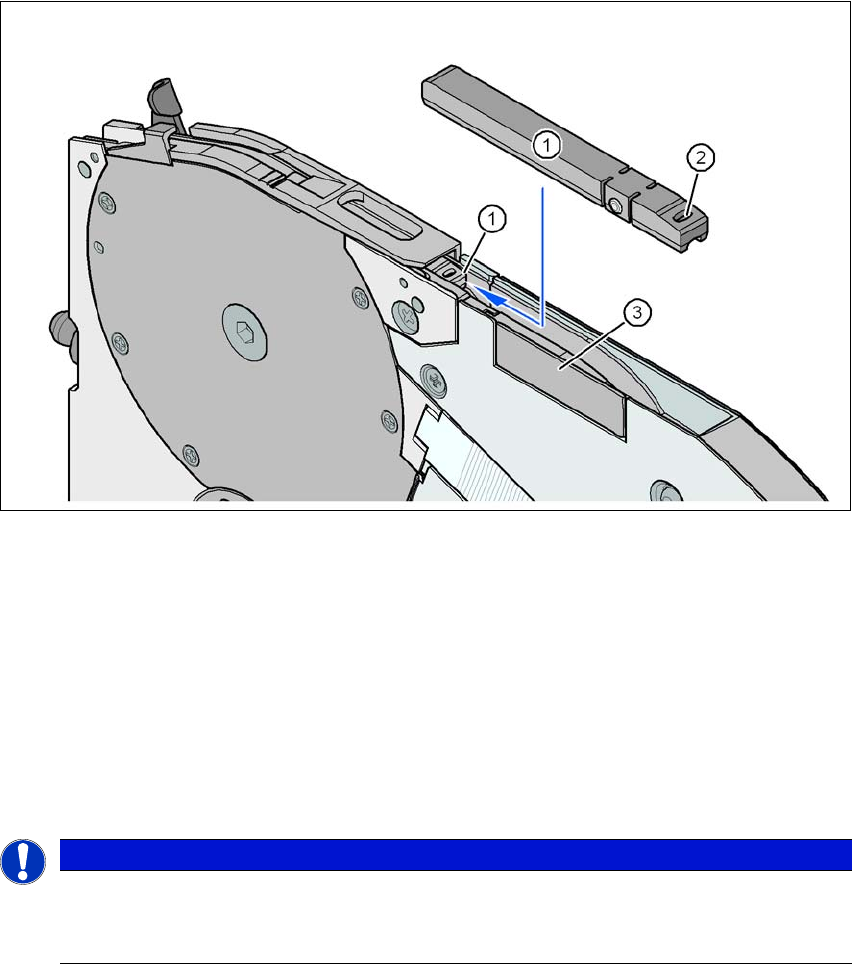
Fig. 5.11 - 7 SIPLACE SmartFeeder 8 mm E - tape support
(1) Tape support, removable
(2) Oval opening in the tape support
The SIPLACE SmartFeeder E is equipped with a tape support (item 1 in fig. 5.11 - 7). It can easily
be removed if necessary.
Insert the tang of a watchmaker's screwdriver into the oval opening (item 2 in fig. 5.11 - 7) in
the tape support and pull the tape support out against the direction of travel of the tape.
When you insert the tape support, make sure that it engages in its desired position.
5
PLEASE NOTE
Constant Z pickup height and reduction of time used to correct pickup heights
For all components size 0402 and smaller, always insert the tape support (item 1 in
fig. 5.11 - 7) into the feeder module.
User manual SIPLACE E 5 Working with the machine
From software version SC 708.0 12/2014 Edition 5.12 Observing displays on the SIPLACE SmartFeeder E
239
5.12 Observing displays on the SIPLACE SmartFeeder E
5.12.1 LED display
The SIPLACE SmartFeeder E have a LED display, to indicate the operating states for each track.
5
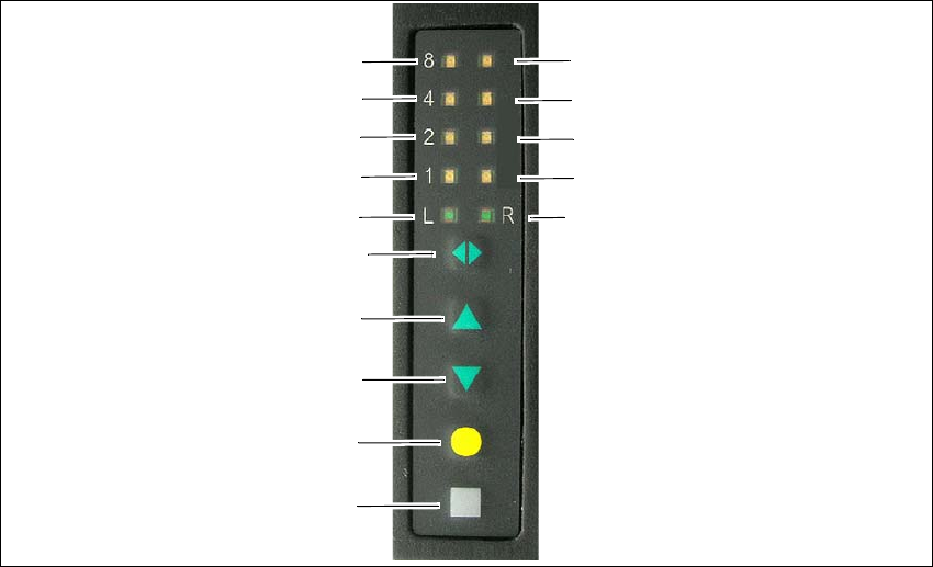
Fig. 5.12 - 1 Buttons and LED display: example of SIPLACE SmartFeeder 2x8mm E module shown
(1) SET button
(2) FOIL button
(3) BACK button
(4) FORWARD button
(5) Track change button for switching between right and left
(6) LED L left track active
(7) LED 1 mm increment for left track
(8) LED 2 mm increment for left track
(9) LED 4 mm increment for left track
(10) LED 8 mm increment for left track
(11) LED R right track active
(12) LED 1 mm increment for right track
(13) LED 2 mm increment for right track
(14) LED 4 mm increment for right track
(15) LED 8 mm increment for right track
(1)
(2)
(3)
(4)
(5)
(6)
(7)
(8)
(9)
(10)
(15)
(14)
(13)
(12)
(11)