00197674-01-UM-E-Series-EN-02-2015.pdf - 第282页
6 Station extensions User manual SIPLACE E 6.1 Nozzle changer From software version SC 708.0 12/2014 Editio n 282 6 Press the magazine dow n evenly so that th e snap fas tener balls engage in all the snap fas - teners …
User manual SIPLACE E 6 Station extensions
From software version SC 708.0 12/2014 Edition 6.1 Nozzle changer
281
6
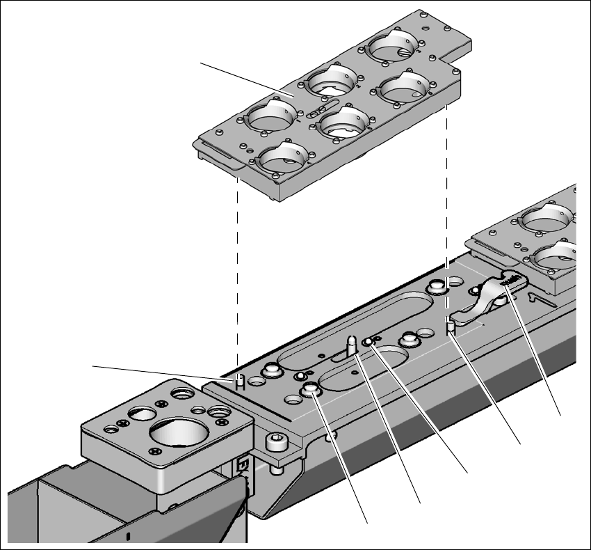
Fig. 6.1 - 20 Nozzle changer for the SIPLACE CP14 - changing the magazine
(1) Lever for raising the magazine
(2) Parallel pin, engages in the hole in the magazine
(3) Spring pin (3 x) for triggering the microswitch
(4) Pin of the slide mechanism, moves the locking plate
(5) Ball of snap fastener
(6) Parallel pin, engages in the slot in the magazine
(7) Magazine
Place the magazine on the snap fastener balls (item 5 in fig. 6.1 - 5, page 258).
(1)
(3)
(4)
(5)
(7)
(6)
(2)

6 Station extensions User manual SIPLACE E
6.1 Nozzle changer From software version SC 708.0 12/2014 Edition
282
6
Press the magazine down evenly so that the snap fastener balls engage in all the snap fas-
teners at the same time.
PLEASE NOTE
6
Before inserting, align the magazine so that the centering pins (items 2 and 6 in fig.
6.1 - 5, page 258) slide into the centering holes and slot.
User manual SIPLACE E 6 Station extensions
From software version SC 708.0 12/2014 Edition 6.2 Operator panel (HMI) on location 2
283
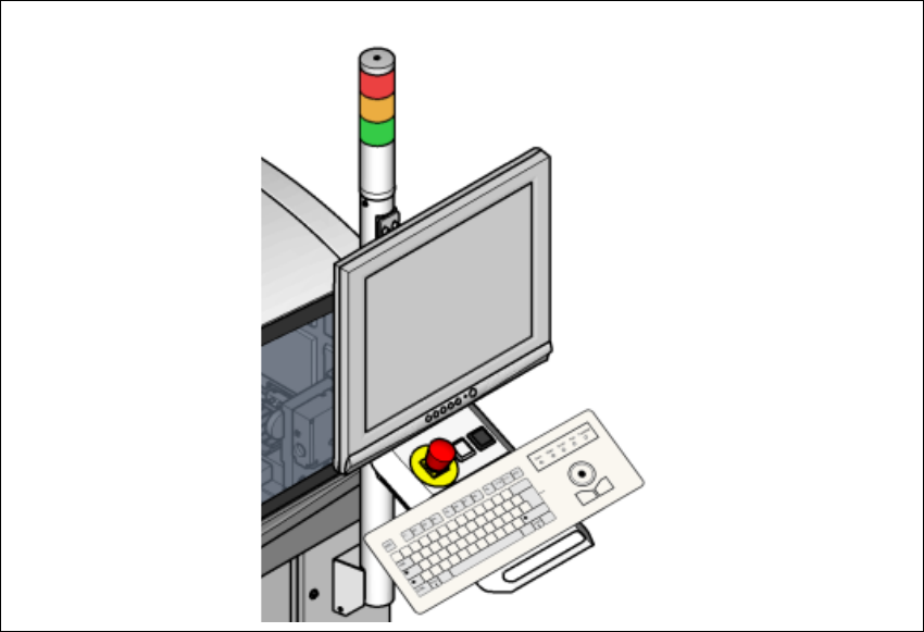
6.2 Operator panel (HMI) on location 2
Item no. 03113590-xx Human-Machine-Interface, loc2
For machines with only one operator panel (HMI) on location 1, you can retrofit an additional HMI
to location 2.
6
Fig. 6.2 - 1 Operator panel (HMI) on location 2