00195722-0102_UM_X-Serie_SR605_EN.pdf - 第117页
User Manual SIPLACE X-Series 3 Technical data for the machine From software version SR.605.xx 07/2008 EN Edition 3.3 Dimensions and weight 117 3.3.5 Center of gravity 3 3 3 Fig. 3.3 - 8 Center of gravity of the X-series …
3 Technical data for the machine User Manual SIPLACE X-Series
3.3 Dimensions and weight From software version SR.605.xx 07/2008 EN Edition
116
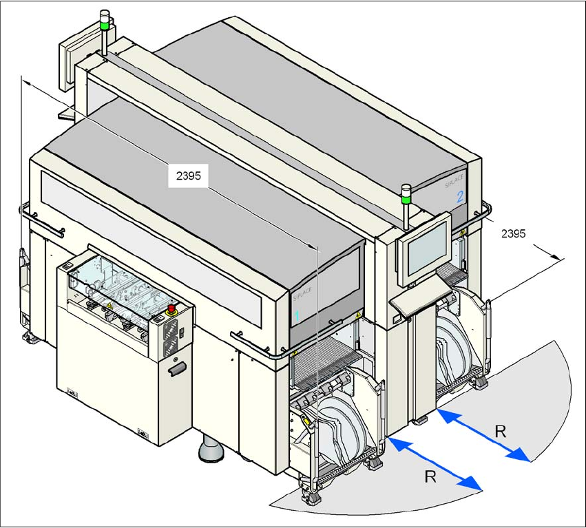
3.3.4.3 Maneuvering distance for the component trolley on the X2 machine
3
3
Fig. 3.3 - 7 Maneuvering distance for the component trolley on the X2 machine
The maneuvering distance R of the component trolley on the X2 machine is:
– at locations 2 and 4
600 mm with the handles folded down or
900 mm with the handles folded up
– at location 1 and 3
750 mm with the handles folded down or
1050 mm with the handles folded up.
User Manual SIPLACE X-Series 3 Technical data for the machine
From software version SR.605.xx 07/2008 EN Edition 3.3 Dimensions and weight
117
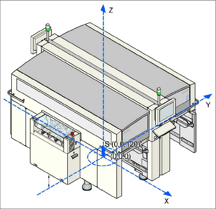
3.3.5 Center of gravity
3
3
3
Fig. 3.3 - 8 Center of gravity of the X-series machines in millimeters
3
X coordinate 0 mm
Y coordinate 0 mm
Z coordinate 120 mm high
These center of gravity coordinates relate to placement systems with a PCB conveyor height of
830 mm.
3 Technical data for the machine User Manual SIPLACE X-Series
3.4 Overview of the modules From software version SR.605.xx 07/2008 EN Edition
118
3.4 Overview of the modules
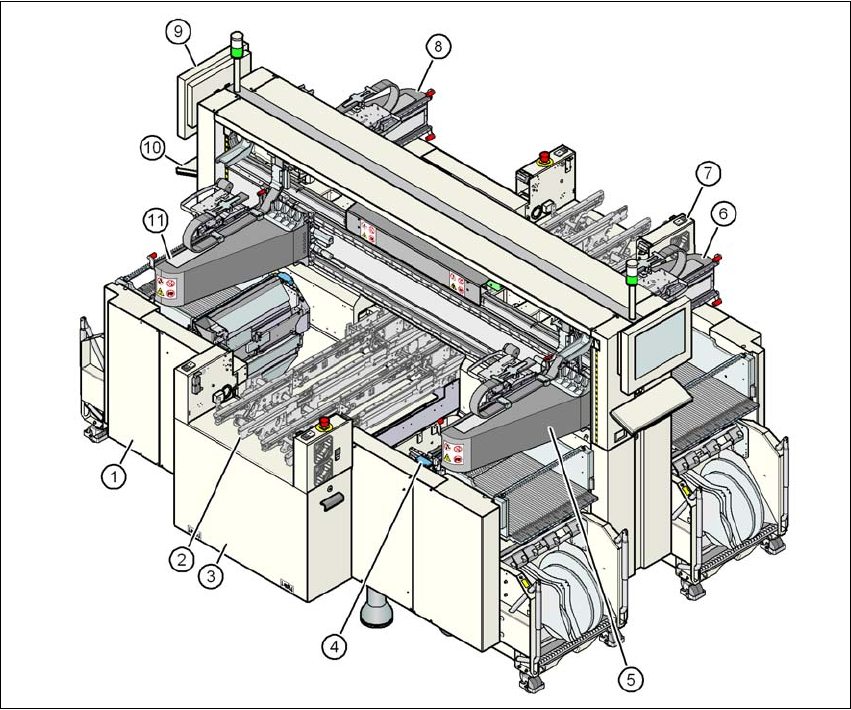
3.4.1 Overview of the modules SIPLACE X4
3
Fig. 3.4 - 1 X4 placement machine - overview of the modules
(1) Machine frame
(2) PCB conveyor (flexible dual conveyor)
(3) Extension kit on the PCB input side
(4) Component trolley docking unit, tape cutter, used tape channel (4x)
(5) Gantry 1 with placement head
(6) Gantry 2 with placement head
(7) Extension kit on the PCB output side
(8) Gantry 3 with placement head
(9) Monitor (2x)
(10) Keyboard (2x)
(11) Gantry 4 with placement head