00195722-0102_UM_X-Serie_SR605_EN.pdf - 第154页
3 Technical data for the machine User Manual SIPLACE X-Series 3.8 Vision system From software ve rsion SR.605.xx 07/2008 EN Edition 154 3.8.2 Assembly positions for the stationa ry cameras - IC came ra and FC camera 3.8.…

User Manual SIPLACE X-Series 3 Technical data for the machine
From software version SR.605.xx 07/2008 EN Edition 3.8 Vision system
153
3.8 Vision system
3.8.1 Structure
A component camera is integrated into each Collect&Place head (see Fig. 3.5 - 2 page 122, fig.
3.5 - 4
page 126 and fig. 3.5 - 6 page 130). The stationary P&P component vision camera (type
33) 55 x 45 digital for the TwinHead is permanently fixed to the machine frame.
The component vision module is used to determine:
– the precise position of the components at the nozzle and
– the geometry of the package form.
The PCB vision module uses fiducials on the PCBs to determine:
– the position of the PCB,
– its rotation angle
– and the PCB skew.
The PCB cameras are fixed to the bottom of the gantries. They use fiducials on the feeder mod-
ules to determine the exact pick-up position of components, which is particularly important for
small components.
WARNING
RISK OF HEAD CRASH 3
When the placement head is changed from the TwinHead to the Collect&Place head, the Twin-
Head's stationary component vision camera, P&P (type 33) 55 x 45, and stationary P&P compo-
nent vision camera (type 25) 16 x 16 digital must be removed, otherwise the Collect&Place head
will collide with the camera housings.
3 Technical data for the machine User Manual SIPLACE X-Series
3.8 Vision system From software version SR.605.xx 07/2008 EN Edition
154
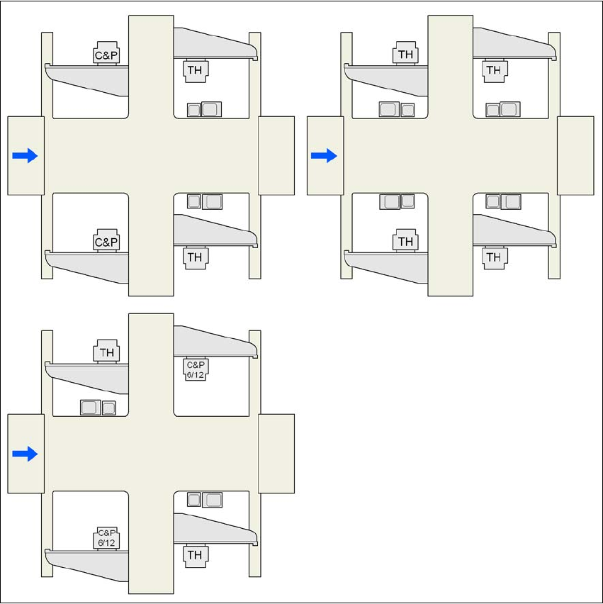
3.8.2 Assembly positions for the stationary cameras - IC camera and FC camera
3.8.2.1 IC and FC cameras on the X4 placement machine
3
Fig. 3.8 - 1 IC and FC cameras on the X4 placement machine
C&P C&P20A or C&P12 or C&P6
C&P6/12 6-segment Collect&Place head or 12-segment Collect&Place head
TH TwinHead
25 FC camera, type 25
33 IC camera, type 33
G1, G2, G3, G4 Gantry 1, gantry 2, gantry 3, gantry 4
33 and 25
25 and 33
25 or 33 33 or 25
33 or 25
25 or 33
25 or 33
G3
G3
G4
G4
G1
G2
G2
G1
G4
G3
G2
G1
25 or 33
User Manual SIPLACE X-Series 3 Technical data for the machine
From software version SR.605.xx 07/2008 EN Edition 3.8 Vision system
155
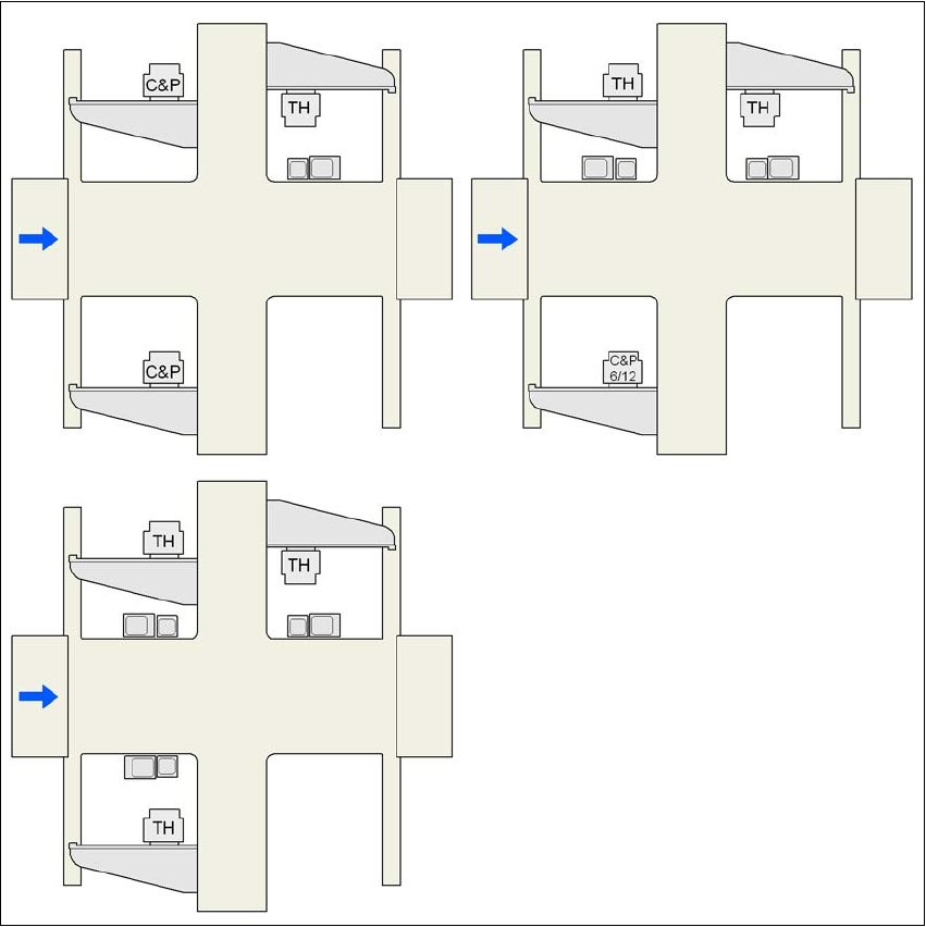
3.8.2.2 IC and FC cameras on the X3 placement machine
3
Fig. 3.8 - 2 IC and FC cameras on the X3 placement machine
C&P C&P20A or C&P12 or C&P6
C&P6/12 6-segment Collect&Place head or 12-segment Collect&Place head
TH TwinHead
25 FC camera, type 25
33 IC camera, type 33
G1, G3, G4 Gantry 1, gantry 3, gantry 4
33 or 25
25 and 33
25 and 33 33 and 25 25 and 33
33 or 25
G3 G3
G4
G4
G1
G1
G4
G3
G1