00195722-0102_UM_X-Serie_SR605_EN.pdf - 第156页
3 Technical data for the machine User Manual SIPLACE X-Series 3.8 Vision system From software ve rsion SR.605.xx 07/2008 EN Edition 156 3.8.2.3 IC and FC cameras on the X2 placement machine 3 Fig. 3.8 - 3 IC and FC camer…
User Manual SIPLACE X-Series 3 Technical data for the machine
From software version SR.605.xx 07/2008 EN Edition 3.8 Vision system
155
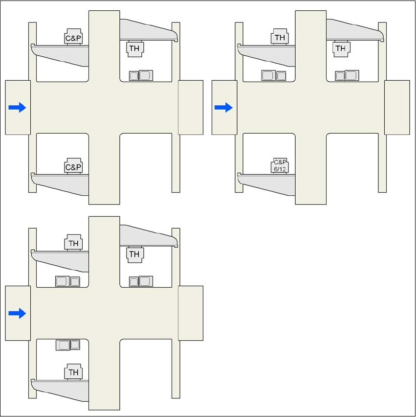
3.8.2.2 IC and FC cameras on the X3 placement machine
3
Fig. 3.8 - 2 IC and FC cameras on the X3 placement machine
C&P C&P20A or C&P12 or C&P6
C&P6/12 6-segment Collect&Place head or 12-segment Collect&Place head
TH TwinHead
25 FC camera, type 25
33 IC camera, type 33
G1, G3, G4 Gantry 1, gantry 3, gantry 4
33 or 25
25 and 33
25 and 33 33 and 25 25 and 33
33 or 25
G3 G3
G4
G4
G1
G1
G4
G3
G1
3 Technical data for the machine User Manual SIPLACE X-Series
3.8 Vision system From software version SR.605.xx 07/2008 EN Edition
156
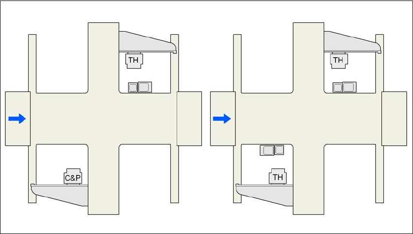
3.8.2.3 IC and FC cameras on the X2 placement machine
3
Fig. 3.8 - 3 IC and FC cameras on the X2 placement machine
C&P C&P20A or C&P12 or C&P6
C&P6/12 6-segment Collect&Place head or 12-segment Collect&Place head
TH TwinHead
25 FC camera, type 25
33 IC camera, type 33
G1, G3 Gantry 1, gantry 3
25 and 33
33 and 25
25 and 33
G3 G3
G1
G1
User Manual SIPLACE X-Series 3 Technical data for the machine
From software version SR.605.xx 07/2008 EN Edition 3.8 Vision system
157
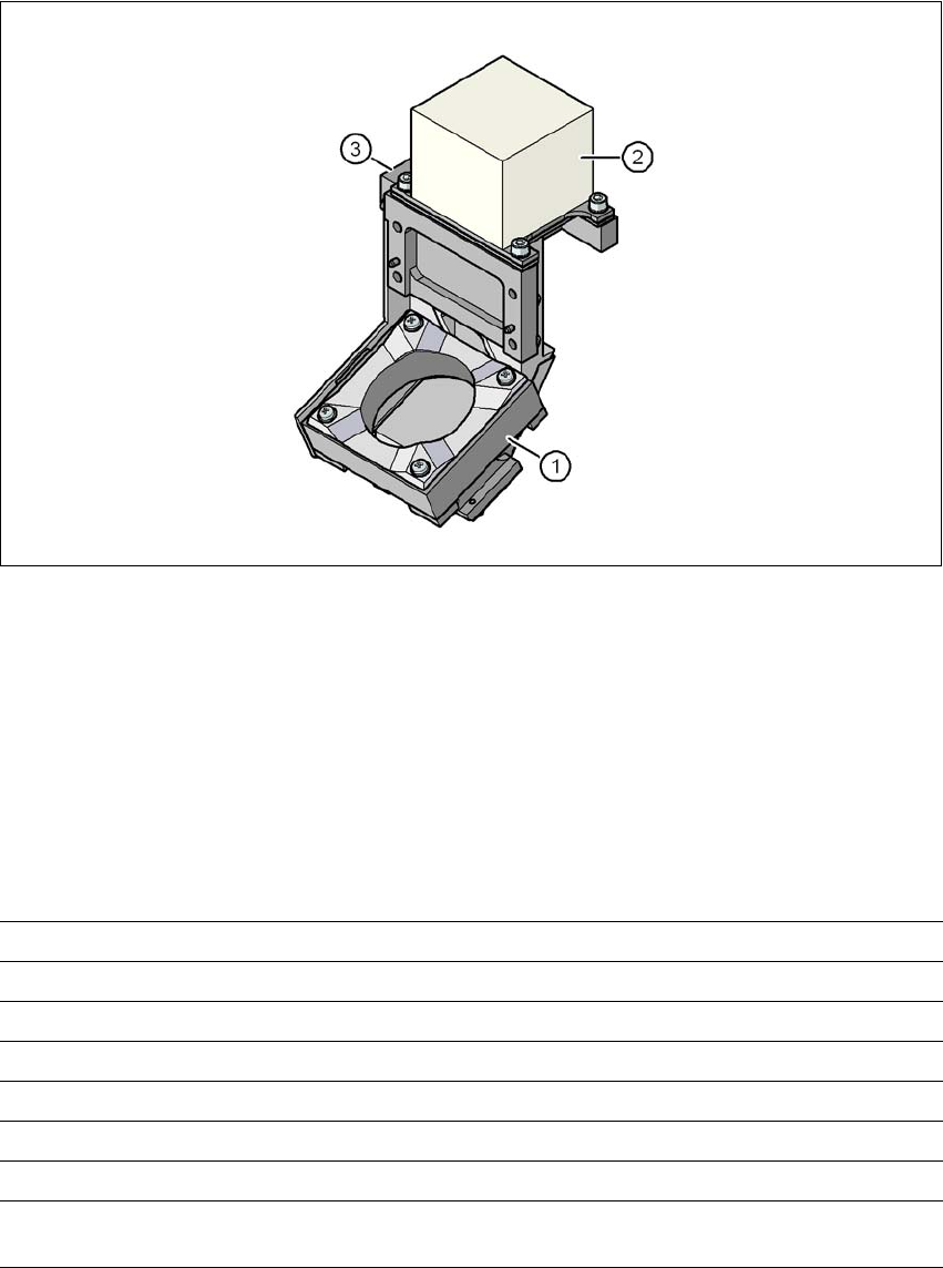
3.8.3 C&P component camera, type 23, 6 x 6, digital
3.8.3.1 Structure
3
Fig. 3.8 - 4 C&P component camera, type 23, 6 x 6, digital
3
(1) Component camera lens and illumination
(2) Camera amplifier
(3) Illumination control
3.8.3.2 Technical data
3
Component dimensions 0.18 x 0.18 mm² to 6 x 6 mm²
Range of components 01005 to 6 x 6 mm²
Min. lead pitch 0.25 mm
Min. lead width 0.1 mm
Min. ball pitch 0.4 mm
Min. ball diameter 0.2 mm
Field of vision 8.4 x 8.4 mm²
Method of illumination Front-illumination (5 levels, programmable as re-
quired)