00195722-0102_UM_X-Serie_SR605_EN.pdf - 第177页
User Manual SIPLACE X-Series 3 Technical data for the machine From software version SR.605.xx 07/2008 EN Edition 3.9 X feeder modules for the component trolle y from the SIPLACE X-series 177 3.9.3 X linear dipping unit (…
3 Technical data for the machine User Manual SIPLACE X-Series
3.9 X feeder modules for the component trolley from the SIPLACE X-series From software version SR.605.xx 07/2008 EN Edition
176
3.9.2.9 88 mm X tape feeder module
3
Fig. 3.9 - 11 88 mm X tape feeder module
3
3
3
88 mm X tape feeder module Item no. 00141278-xx
88 mm X tape feeder module with splice sensor Item no. 00141298-xx
Width 105.2 mm
Feeder module locations filled 9
Conveyor increment From 4 mm to 96 mm in 4 mm increments
Changeover time for the component tape < 45 s
Changeover time for the pre-set feeder module
on the machine
≤ 8 s
User Manual SIPLACE X-Series 3 Technical data for the machine
From software version SR.605.xx 07/2008 EN Edition 3.9 X feeder modules for the component trolley from the SIPLACE X-series
177
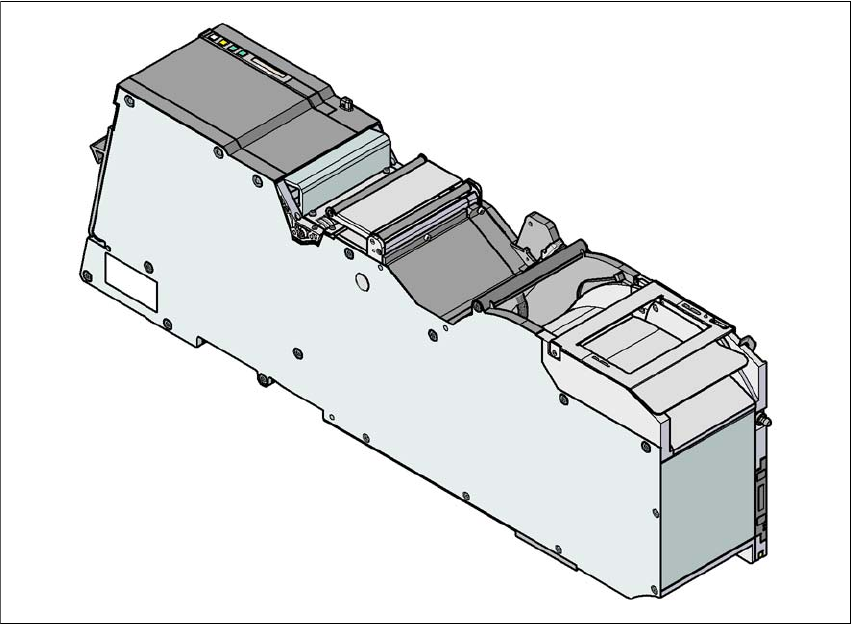
3.9.3 X linear dipping unit (LDU X)
Item no. 00117011-xx Linear dip module for flux / LDU-X
Item no. dip plates see Section 3.9.3.3
, page 179
3
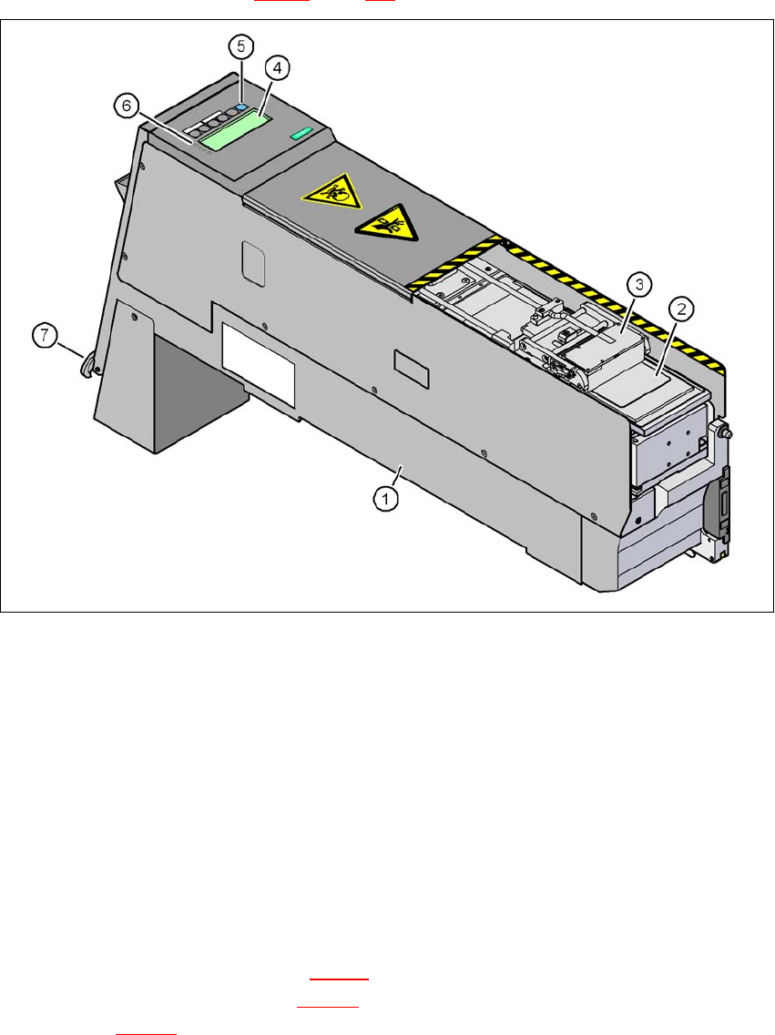
Fig. 3.9 - 12 Linear Dipping Unit (LDU X)
(1) LDU X
(2) Dip plate
(3) Flux container
(4) Display panel (4 lines each with 20 characters)
(5) Operator panel with 6 membrane keys
(6) LED for status displays
(7) EMERGENCY OFF button
3.9.3.1 Description
The X linear dipping unit (item 1 in Fig. 3.9 - 12) is used to wet flip-chip and CSP components with
flux. The flux container item 3 in Fig. 3.9 - 12
) slides with a linear movement over the dip plate
(item 2 in Fig. 3.9 - 12
) and applies the flux at a defined layer thickness in the depression in the
dip plate. The parameters for wetting a component with flux are prescribed in SIPLACE Pro. The

3 Technical data for the machine User Manual SIPLACE X-Series
3.9 X feeder modules for the component trolley from the SIPLACE X-series From software version SR.605.xx 07/2008 EN Edition
178
component is wetted and then the flux layer is renewed. This sequence guarantees consistent
processing conditions for the components.
The individual menus for actions and operating parameters are displayed in the display panel
(item 4 in Fig. 3.9 - 12
, page 177). The menus can be selected or a parameter modified and stored
using the buttons on the operator panel (item 5 in Fig. 3.9 - 12
, page 177). The 4 LEDs (item 6 in
Fig. 3.9 - 12
, page 177) of the display panel signalizes the status of the LDU-X. The LDU-X is
switched off immediately when the EMERGENCY OFF button is pressed (item 7 in Fig. 3.9 - 12
,
page 177
).
The LDU X is suitable for the following placement heads:
6-segment Collect&Place head
12-segment Collect&Place head
TwinHead 3
The LDU-X is considered as an independent feeder module types in the set-up. The module can
only be set up on a component trolley of the SIPLACE X-series. An implemented warming function
allows the viscosity of the flux to be altered. The LDU-X can be operated outside the machines
using the energy and data interface for X feeder modules (see Section 3.9.5
, page 183) for test
purposes.
3.9.3.2 Technical data
Further technical data and details can be found in the "SIPLACE LDU-X" user manual.
Filled 8mm locations on the CO trolley of the
SIPLACE X-series
9
Component size a max. of 55 x 55 mm², depending on the
placement head type;
a max. of 45 x 45 mm² for TwinHead
The adjustable flux layer thickness 15 - 260 μm
Tolerance of the layer thicknesses ± 5 μm ... ± 10 µm
Time for applying the flux to the dip plate > 3s
Component dipping time adjustable using the software
Flux Indium TACFlux 010 / 013
Kester TSF-6502 / 6522
Alphametals OM338 / OM338PT
Almit BM1 RMA
Cookson WS 3018lv u.a.