00195722-0102_UM_X-Serie_SR605_EN.pdf - 第186页
3 Technical data for the machine User Manual SIPLACE X-Series 3.9 X feeder modules for the component trolley from the SIPLAC E X-series From software version SR.605.xx 07/2008 EN Edition 186 3.9.6.1 T echnical data 3 3.9…
User Manual SIPLACE X-Series 3 Technical data for the machine
From software version SR.605.xx 07/2008 EN Edition 3.9 X feeder modules for the component trolley from the SIPLACE X-series
185
3.9.6 Waffle-pack tray holder for the component trolley from the SIPLACE X-series
Item no. 00141285-xx Waffle-pack tray holder, X-series
3
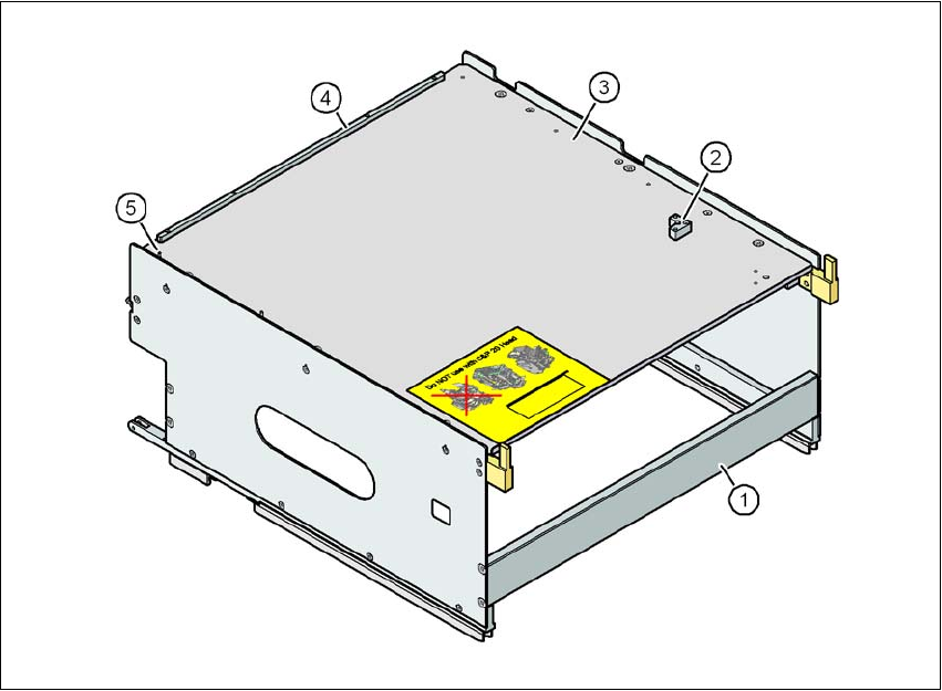
Fig. 3.9 - 17 Waffle-pack tray holder
(1) Waffle-pack tray holder from the SIPLACE X-series
(2) Retaining bracket for a second JEDEC waffle-pack tray
(3) Waffle-pack tray carrier
(4) Stop bars for the JEDEC waffle-pack tray
(5) Dowel pin - Zero point for the JEDEC waffle-pack tray
3
Individually fitted JEDEC waffle-pack trays or waffle-pack magazines can be fixed to the waffle-
pack tray carrier using magnets. If two JEDEC waffle-pack trays are fitted, you must fix them with
locking and retaining rails, as used for the waffle-pack tray carrier on the MTC.
Parts: Item no.:
Magnet 00316593-xx
Locking and retaining rail for JEDEC trays 00372615-xx

3 Technical data for the machine User Manual SIPLACE X-Series
3.9 X feeder modules for the component trolley from the SIPLACE X-series From software version SR.605.xx 07/2008 EN Edition
186
3.9.6.1 Technical data
3
3.9.6.2 Number of waffle-pack trays per location and machine
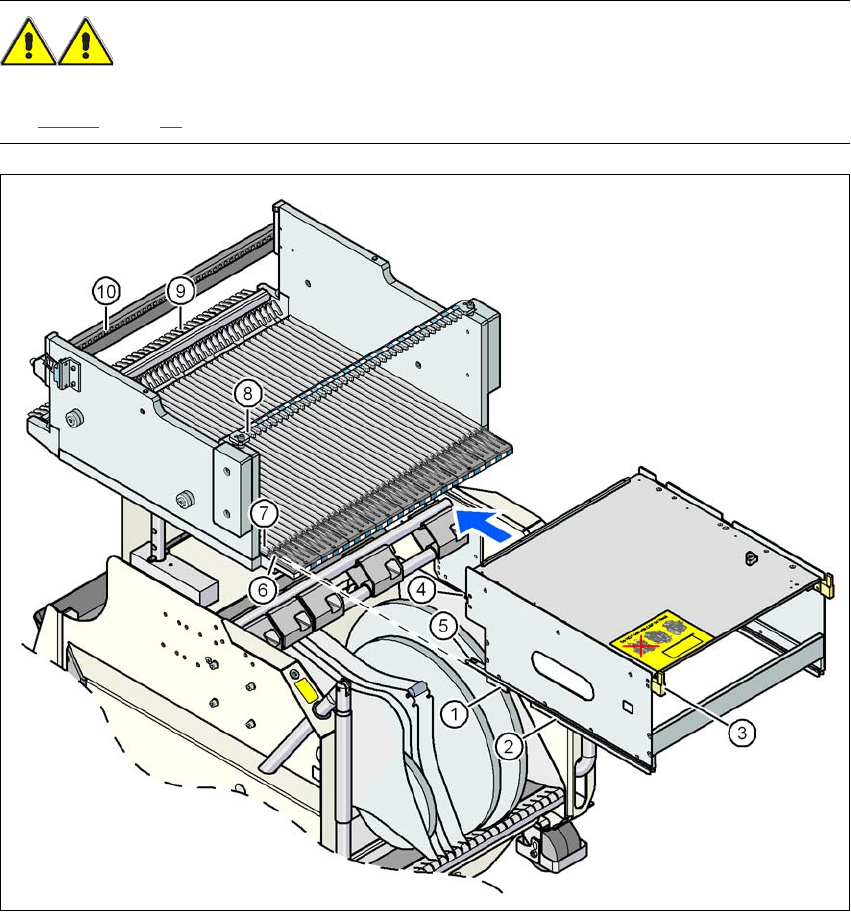
3.9.6.3 Using the waffle-pack tray holder on the X-series component trolley
→ Place the two front slider guides (item 1 in Fig. 3.9 - 18, page 187) of the holder on the insertion
aid (item 6 in Fig. 3.9 - 18
, page 187).
→ Push the holder forward along the guide profiles (item 7 in Fig. 3.9 - 18
, page 187). The holder
will slide with its front (item 1) and rear slider guides (item 2 in Fig. 3.9 - 18
, page 187) on the
guide profiles.
→ Carefully push the holder further until the two "front" centering pins (item 4 in Fig. 3.9 - 18
, page
187
) disappear into the centering holes (item 10 in Fig. 3.9 - 18, page 187).
→ Watch the two "back" centering pins (item 3 in Fig. 3.9 - 18
, page 187) on the holder. They must
slide easily into the recesses (item 8 in Fig. 3.9 - 18
, page 187) on the centering bar.
→ When the holder is at the stop position, the locking tabs (item 9 in Fig. 3.9 - 18
, page 187) en-
gage on the locking rollers (item 5) on the holder.
3
The waffle-pack tray holder can be locked and released via the user interface. It is therefore pos-
sible to change the holder while placement is in progress.
Dimensions L x W x H 429 mm x 376 mm x 200 mm
Location filled on the component table 32 locations
a
a) X feeder modules can be positioned at the remaining 8 locations. If locking and retaining rails are used, how-
ever, the fixing lever projecting at the side reduces the available locations to 6.
Positioning option on the X-series machines Locations 2 and 4
Software
Station software SR.601.xx or later
Programming system SIPLACE Pro 3.0 or later
Range of placement heads TwinHead, C&P6, C&P12
Placement machine Location 2 Location 4
X4 1 1
X3 2 1
X2 2 2
User Manual SIPLACE X-Series 3 Technical data for the machine
From software version SR.605.xx 07/2008 EN Edition 3.9 X feeder modules for the component trolley from the SIPLACE X-series
187
WARNING 3
Please follow the safety instructions for processing capacitors based on powdered metal in Sec-
tion 2.6.5.1, page 85.
3
Fig. 3.9 - 18 Inserting a waffle-pack tray holder for the component trolley from the SIPLACE X-series
(1) Front slider guide (6) Insertion aid
(2) Back slider guide (7) Slide bar (omega profile)
(3) "Back" centering pin (8) Recess in the centering bar for holding the
"back" centering pin
(4) "Front" centering pin (9) Locking latches
(5) Locking roller (10) Centering holes on the component table for
holding the "front" centering pin