00195722-0102_UM_X-Serie_SR605_EN.pdf - 第187页
User Manual SIPLACE X-Series 3 Technical data for the machine From software version SR.605.xx 07/2008 EN Edition 3.9 X feeder modules for the component trolle y from the SIPLACE X-series 187 W ARNING 3 Please follow the …

3 Technical data for the machine User Manual SIPLACE X-Series
3.9 X feeder modules for the component trolley from the SIPLACE X-series From software version SR.605.xx 07/2008 EN Edition
186
3.9.6.1 Technical data
3
3.9.6.2 Number of waffle-pack trays per location and machine
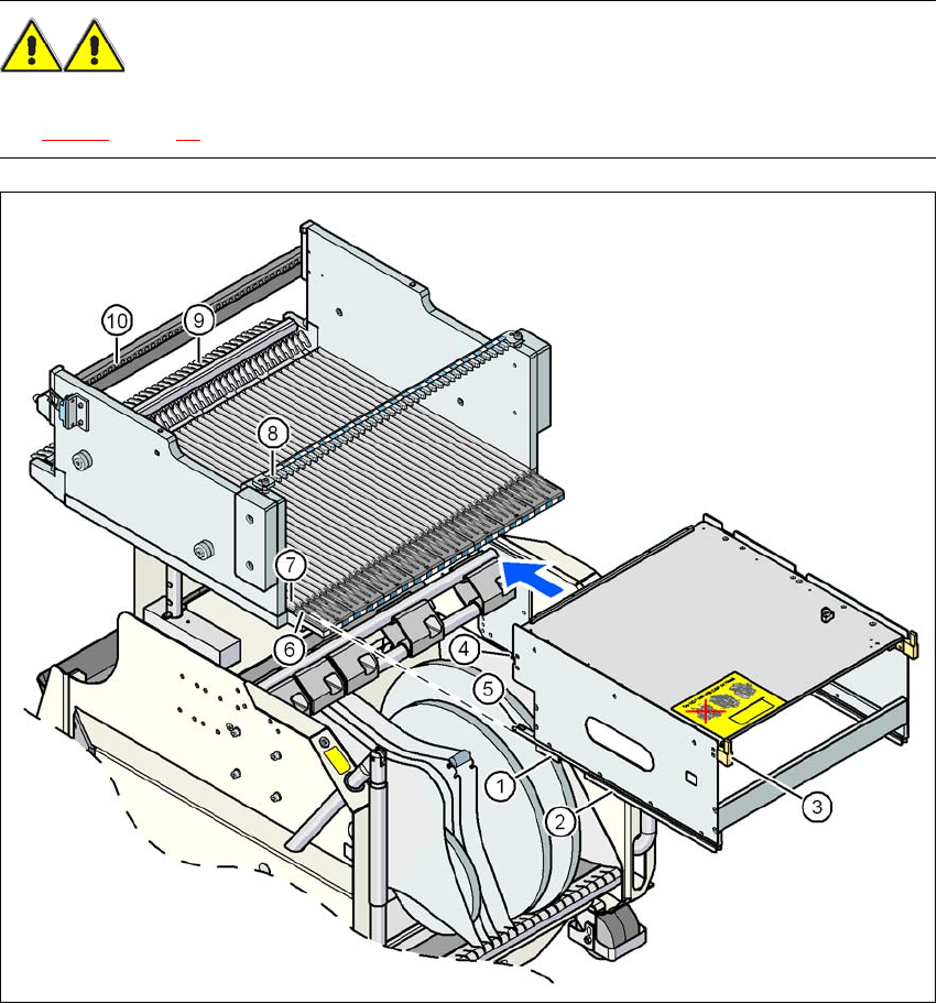
3.9.6.3 Using the waffle-pack tray holder on the X-series component trolley
→ Place the two front slider guides (item 1 in Fig. 3.9 - 18, page 187) of the holder on the insertion
aid (item 6 in Fig. 3.9 - 18
, page 187).
→ Push the holder forward along the guide profiles (item 7 in Fig. 3.9 - 18
, page 187). The holder
will slide with its front (item 1) and rear slider guides (item 2 in Fig. 3.9 - 18
, page 187) on the
guide profiles.
→ Carefully push the holder further until the two "front" centering pins (item 4 in Fig. 3.9 - 18
, page
187
) disappear into the centering holes (item 10 in Fig. 3.9 - 18, page 187).
→ Watch the two "back" centering pins (item 3 in Fig. 3.9 - 18
, page 187) on the holder. They must
slide easily into the recesses (item 8 in Fig. 3.9 - 18
, page 187) on the centering bar.
→ When the holder is at the stop position, the locking tabs (item 9 in Fig. 3.9 - 18
, page 187) en-
gage on the locking rollers (item 5) on the holder.
3
The waffle-pack tray holder can be locked and released via the user interface. It is therefore pos-
sible to change the holder while placement is in progress.
Dimensions L x W x H 429 mm x 376 mm x 200 mm
Location filled on the component table 32 locations
a
a) X feeder modules can be positioned at the remaining 8 locations. If locking and retaining rails are used, how-
ever, the fixing lever projecting at the side reduces the available locations to 6.
Positioning option on the X-series machines Locations 2 and 4
Software
Station software SR.601.xx or later
Programming system SIPLACE Pro 3.0 or later
Range of placement heads TwinHead, C&P6, C&P12
Placement machine Location 2 Location 4
X4 1 1
X3 2 1
X2 2 2
User Manual SIPLACE X-Series 3 Technical data for the machine
From software version SR.605.xx 07/2008 EN Edition 3.9 X feeder modules for the component trolley from the SIPLACE X-series
187
WARNING 3
Please follow the safety instructions for processing capacitors based on powdered metal in Sec-
tion 2.6.5.1, page 85.
3
Fig. 3.9 - 18 Inserting a waffle-pack tray holder for the component trolley from the SIPLACE X-series
(1) Front slider guide (6) Insertion aid
(2) Back slider guide (7) Slide bar (omega profile)
(3) "Back" centering pin (8) Recess in the centering bar for holding the
"back" centering pin
(4) "Front" centering pin (9) Locking latches
(5) Locking roller (10) Centering holes on the component table for
holding the "front" centering pin

3 Technical data for the machine User Manual SIPLACE X-Series
3.10 S feeder modules for the SIPLACE HF component trolley From software version SR.605.xx 07/2008 EN Edition
188
3.10 S feeder modules for the SIPLACE HF component
trolley
The following feeder modules are currently available to provide the placement machine with the
various component types:
3.10.1 Tape feeder modules
– 8 mm SII feeder module
– 3 x 8 mm S feeder module
– 3 x 8 mm S feeder module for 0201/0402 components in paper tape
– 3 x 8 mm S feeder module SL
a
as of 0201 components in paper tape or blister tape
– S feeder module for 12/16 mm, 24/32 mm, 44 mm, 56 mm, 72 mm and 88 mm
– S DP feeder module for deep pockets, 24/32 mm, 44 mm and 56 mm
3.10.2 Other feeder modules
– Linear vibratory feeder, type 3
– Bulk case feeder module
– Surf tape feeder module for 8 mm, 12 mm and 16 mm
– Waffle-pack tray holder
3.10.3 Description
These feeder modules can be used to process all components with the most common package
forms, such as bulk cases, stick magazines and taped components.
The most important feature of the modular component feeding system is its great flexibility. For
example, the feeding increment can be set on the feeder module. Paper and blister tapes can be
processed with the tape feeder modules. A small range of feeder module types is sufficient to
place a large range of component types.
The position detection system on the feeder modules can precisely determine the component
pick-up position. The position detection is carried out automatically whenever the feeder module
or component trolley is changed.
The feeder modules can be quickly and easily changed or replaced, even by unskilled personnel.
a) SL = shutterless, that is without any component cover