00195722-0102_UM_X-Serie_SR605_EN.pdf - 第206页
3 Technical data for the machine User Manual SIPLACE X-Series 3.10 S feeder modules for the SIPLACE HF component trolley From software version SR.605.xx 07/2008 EN Edition 206 3.10.8.16 Surf t ape feeder module For placi…
User Manual SIPLACE X-Series 3 Technical data for the machine
From software version SR.605.xx 07/2008 EN Edition 3.10 S feeder modules for the SIPLACE HF component trolley
205
3.10.8.15 Bulk case feeder module
3
Fig. 3.10 - 15 Bulk case feeder module
Item no. 00142318-xx 3
Width 30.6 mm 3
Tracks per feeder module 2 3
Feeder module locations filled 1 3
Maximum number of feeder modules 4 x 15 3
Stock of components Up to 50,000 3
Feeding rails 0402 / 0.5 mm high item no. 00142320-xx 3
0603 / 0.80 mm high item no. 00142322-xx 3
Cycle time < 60 ms 3
The compressed air supply for bulkcase feeder modules is described in Section 3.12.7
, page
231
. 3
3 Technical data for the machine User Manual SIPLACE X-Series
3.10 S feeder modules for the SIPLACE HF component trolley From software version SR.605.xx 07/2008 EN Edition
206
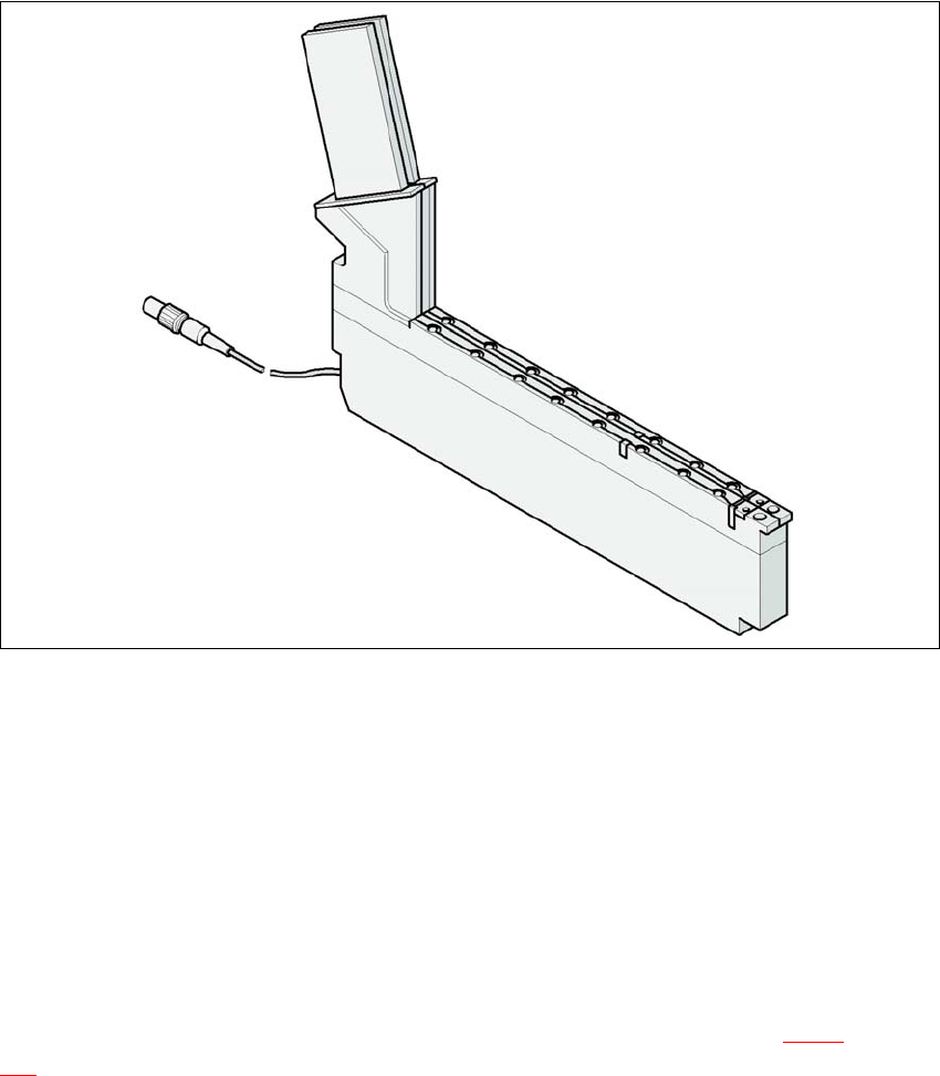
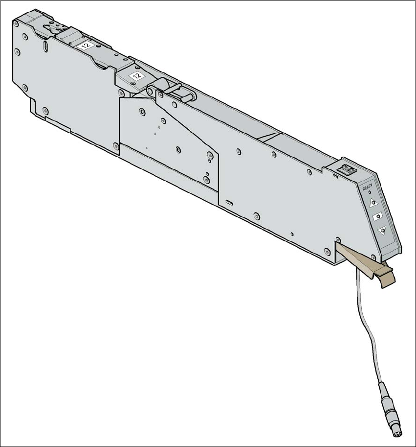
3.10.8.16 Surf tape feeder module
For placing bare dies, you will need the surf tape feeder module for feeding components. There
are versions of these feeder modules for 8 mm tapes and 12 or 16 mm tapes. 3
3
Fig. 3.10 - 16 Surf tape feeder module
3
Handling of the feeder module is described in the operating instructions for feeder modules. 3

User Manual SIPLACE X-Series 3 Technical data for the machine
From software version SR.605.xx 07/2008 EN Edition 3.10 S feeder modules for the SIPLACE HF component trolley
207
Technical data 3
3
3
Parameters for surf tape feeder modules 3
The parameters for the surf tape feeder module can be modified on the SIPLACE Pro computer.
Tape widths 8/12/16 mm
Recommended tape and component
sizes
8 mm: for 1 x 1 mm² - 2.3 x 2.3 mm² components
12 mm: for 2.3 x 2.3 mm² - 5 x 5 mm² components
16 mm: for 3.8 x 3.8 mm² - 9.5 x 9.5 mm² compo-
nents
Packaging accuracy of the bare die on
the surf tape
Bare die size up to 2.3 x 2.3 mm²: +/- 100 µm, 6σ
Bare die size over 2.3 x 2.3 mm²: +/- 200 µm, 6σ
(related to the center of the pocket)
Required distance between the edges of
the bare dies
to the tape pocket Min. 0.4 mm
Pusher needle Single or triple needle depending on the die size
Tape material Metric
Tape standard IEC 286-3, DIN-IEC-286, EIA 481, and JIS C 0806
Tape reel diameter 7" to 15"
Footprint of the feeder module 1 location on the component table