00195722-0102_UM_X-Serie_SR605_EN.pdf - 第210页
3 Technical data for the machine User Manual SIPLACE X-Series 3.10 S feeder modules for the SIPLACE HF component trolley From software version SR.605.xx 07/2008 EN Edition 210 PLEASE NOTE – The waffle-pa ck tray holder c…
User Manual SIPLACE X-Series 3 Technical data for the machine
From software version SR.605.xx 07/2008 EN Edition 3.10 S feeder modules for the SIPLACE HF component trolley
209
3
3.10.9.3 Assembly
3
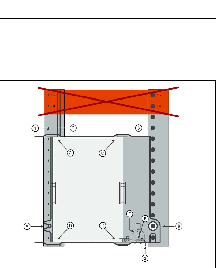
Fig. 3.10 - 17 Installation
(1) Centering pins
(2) Magnetic rail
(3) Centering ball
(14), (15) This position must not be filled.
Positioning options Locations 2 and 4
Range of placement heads TH, C&P6, C&P12
Max. waffle-pack tray height
including components
C&P12
C&P6
TH
12.5 mm
12.5 mm
28.5 mm
3 Technical data for the machine User Manual SIPLACE X-Series
3.10 S feeder modules for the SIPLACE HF component trolley From software version SR.605.xx 07/2008 EN Edition
210
PLEASE NOTE
– The waffle-pack tray holder can only be set up at locations 2 and 4.
– The feeder module positions 14 and 15 on the component table must not be filled.
– The holder and the nozzle changer cannot be used at the same time at location 4.
– The component trolley cannot be docked in/out while the holder is fitted.
3.10.9.4 Assembly
→ Insert the front side of the waffle-pack tray holder into the associated centering pin (A in Fig.
3.10 - 17
, page 209).
→ Then position the hole on the rear side of the waffle-pack tray holder onto the centering ball on
the component table (B in Fig. 3.10 - 17
, page 209).
→ Make sure the waffle-pack tray is resting securely on the component table.
→ Position one side of the waffle-pack tray carrier in the mounting (C in Fig. 3.10 - 17
, page 209).
Then press the other side into the mounting (D in Fig. 3.10 - 17
, page 209).
→ Slide the waffle-pack tray up against the stop (E in Fig. 3.10 - 17
, page 209).
→ Secure the waffle-pack tray carrier by pressing the thrust pad (F in Fig. 3.10 - 17
, page 209)
downwards.
→ To remove the waffle-pack tray carrier, press the thrust pad once more.
PLEASE NOTE
Using the holder for small waffle-pack trays (136mm) a waffle-pack tray (JEDEC or CENELEC
waffle-pack tray) can be fitted directly to the holder, in other words, without a waffle-pack tray car-
rier being used. To do this, change the retainer (G in Fig. 3.10 - 17, page 209). 3
WARNING 3
Please follow the safety instructions for processing capacitors based on powdered metal in Sec-
tion 2.6.5.2, page 86.
3.10.9.5 Changing the retainer
→ Hold the retainer (G in Fig. 3.10 - 17, page 209) firmly. Press the thrust pad downwards (F in
Fig. 3.10 - 17
, page 209) and remove the retainer by pressing it out sideways.
3.10.9.6 Data entry
Define the waffle-pack trays as described in the SIPLACE Pro operating instructions. 3
User Manual SIPLACE X-Series 3 Technical data for the machine
From software version SR.605.xx 07/2008 EN Edition 3.10 S feeder modules for the SIPLACE HF component trolley
211
3.10.10 Dip module for the SIPLACE HF component trolley
Item no. 00117010-xx Dip module for flux and adhesives
3
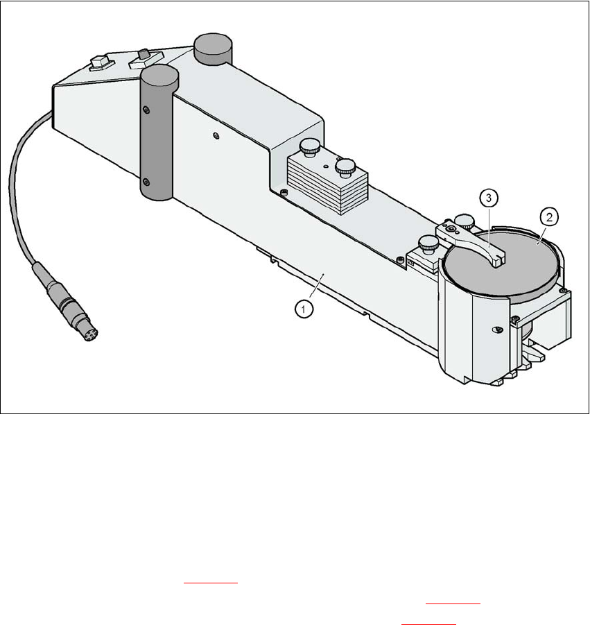
Fig. 3.10 - 18 Dip module
(1) dip module
(2) Rotating plate
(3) Squeegee
3.10.10.1 Description
The dip module (item 1 in Fig. 3.10 - 18) is used to wet flip-chip and CSP components with flux or
conductive adhesive. The flux holder is a rotating plate (item 2 in Fig. 3.10 - 18
) on which a thin
film of flux (e.g. 40 µm) is created with a squeegee (item 3 in Fig. 3.10 - 18
). This method is par-
ticularly suitable for highly viscous (honey-like) fluxes. The amount of flux required for the process
is reduced to a minimum coating thickness since only the undersides of the bumps have to be wet-
ted.