00195722-0102_UM_X-Serie_SR605_EN.pdf - 第213页
User Manual SIPLACE X-Series 3 Technical data for the machine From software version SR.605.xx 07/2008 EN Edition 3.11 SIPLACE X-series component trolley 213 3.1 1 SIPLACE X-series component trolley Item no. 001 19722-xx …
3 Technical data for the machine User Manual SIPLACE X-Series
3.10 S feeder modules for the SIPLACE HF component trolley From software version SR.605.xx 07/2008 EN Edition
212
The Dip module is suitable for the following placement heads:
6-segment Collect&Place head
12-segment Collect&Place head
TwinHead 3
The Dip module is regarded as a separate feeder module type by the set-up optimization. There
is no limit to the number of dip modules at the individual locations.
3.10.10.2 Technical data
Feeder module locations filled 3 3
Component size Max. 36 x 36 mm²
depending on the placement head type 3
Possible coating thicknesses 25, 35, 45, 55, 65, 75 µm 3
Time required to change the coating thickness Less than 1 min. 3
Gap height tolerance ± 5 μm 3
Time for 1 revolution of the table Can be set using the potentiometer from 0 -
10s 3
Component dip time Programmable from 0 - 2s
in 0.1s increments 3
Flux Highly viscous flux, conductive adhesive 3
Further technical data and information on programming can be found in the Betriebsanleitung
DIP-Modul / DIP Module User Manual, item no. 00195065-xx.
3
User Manual SIPLACE X-Series 3 Technical data for the machine
From software version SR.605.xx 07/2008 EN Edition 3.11 SIPLACE X-series component trolley
213
3.11 SIPLACE X-series component trolley
Item no. 00119722-xx CO trolley SIPLACE X-series
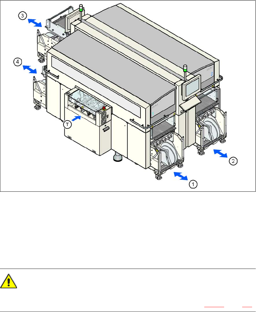
Up to four SIPLACE X-series component trolleys can be docked into the machines from the
SIPLACE X-series. The locations are numbered as shown in the diagram below.
3
Fig. 3.11 - 1 Component trolley locations, SIPLACE X-series
(1) Location 1
(2) Location 2
(3) Location 3
(4) Location 4
(T) PCB direction of travel
CAUTION 3
The component trolleys from the SIPLACE X-series may only be docked into locations at which
the component trolley docking unit for the SIPLACE X-series is installed (Fig. 5.11 - 3, page 360).
3 Technical data for the machine User Manual SIPLACE X-Series
3.11 SIPLACE X-series component trolley From software version SR.605.xx 07/2008 EN Edition
214
The component trolleys are stand-alone modules that can be set up with feeders at an external
set-up area. This means that the production process only has to be interrupted briefly in order to
change the component trolley.
3
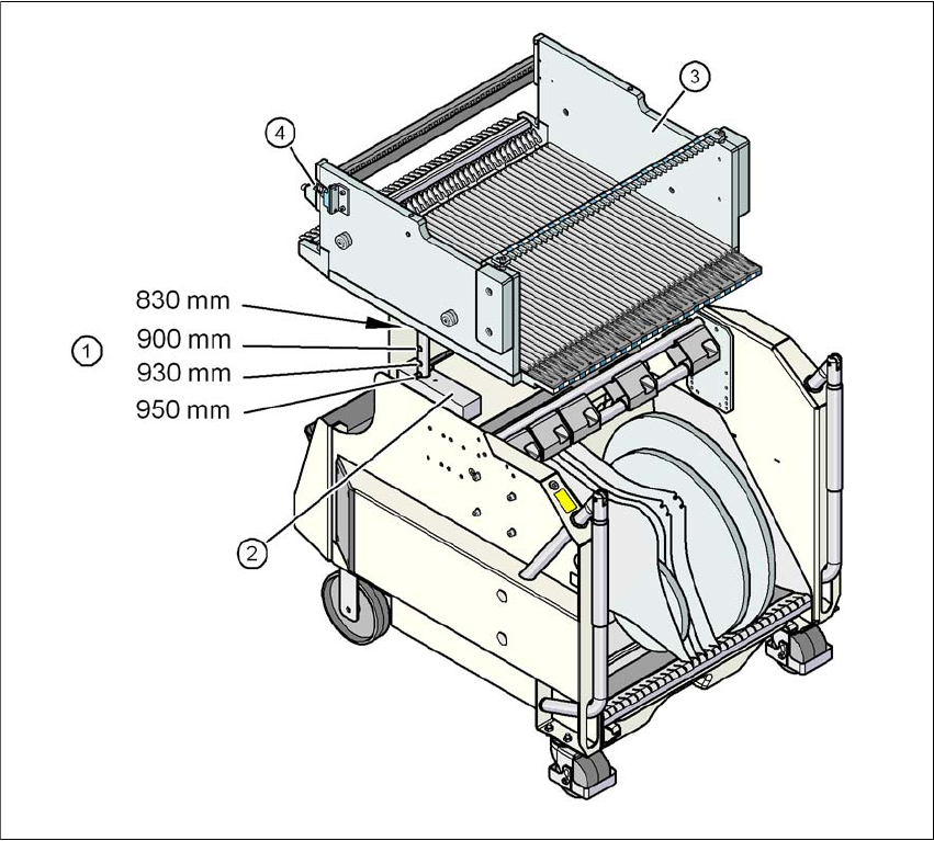
Fig. 3.11 - 2 Component trolley, SIPLACE X-series with a PCB conveyor height of 950 mm
3
(1) Holes for the PCB conveyor heights 900, 930 and 950 mm in the guide columns. For the
830 mm conveyor height, the component table lies on the block (2).
(2) Supporting block
(3) Component table
(4) Contact for switching the safety switch in the component trolley docking unit